Form 44201460
39
Mar 2019
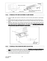
REMOVAL OF SPARK ELECTRODE/FLAME SENSOR
21.2)
1.
Remove the glass panel as shown in Section 21.1). Open the access panel assembly by loosening the
screws.
2.
Disconnect the ignition cable and flame sensor wires (not shown) from the spark electrode/flame sensor.
3.
Remove the screws holding the assembly and slide the spark electrode/flame sensor away from the
heater.
4.
Inspect the ceramic portion of the electrode/flame senors for any cracks. Remove any foreign matter from
the electrode tips and check that the spark gap is .199” (5mm). If the electrode/flame sensor rods are
badly oxidized, replace the electrode/flame sensor in the reverse order. Note: When installed, the flame
sensor rod must have a gap of 1/8” (3mm) to the ceramic surface.
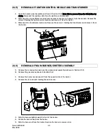
REMOVAL OF MAIN BURNER ORIFICE (INJECTOR)
21.3)
1.
Open the access panel assembly as shown in Section 21.2). Note: This is removed from the illustration for
clarity. Unscrew the main burner orifice from the gas valve manifold using a ½” (12.7mm) end wrench.
2.
Inspect the orifice and clean as necessary with a soft bristle brush.
DO NOT DAMAGE ORIFICE OPENING BY USE OF SOLID OBJECTS.
Содержание 44625000
Страница 37: ...Form 44201460 37 Mar 2019...
Страница 45: ......


