MES SQA-V Скачать руководство пользователя страница 43

     and 

SQA-V 

Service Manual Dec_2019     


43 


5.


A progress bar can now be seen 
on V-Sperm.


6.


The button must remain 

inside the port as described 
above during the ENTIRE 
process of loading the tests


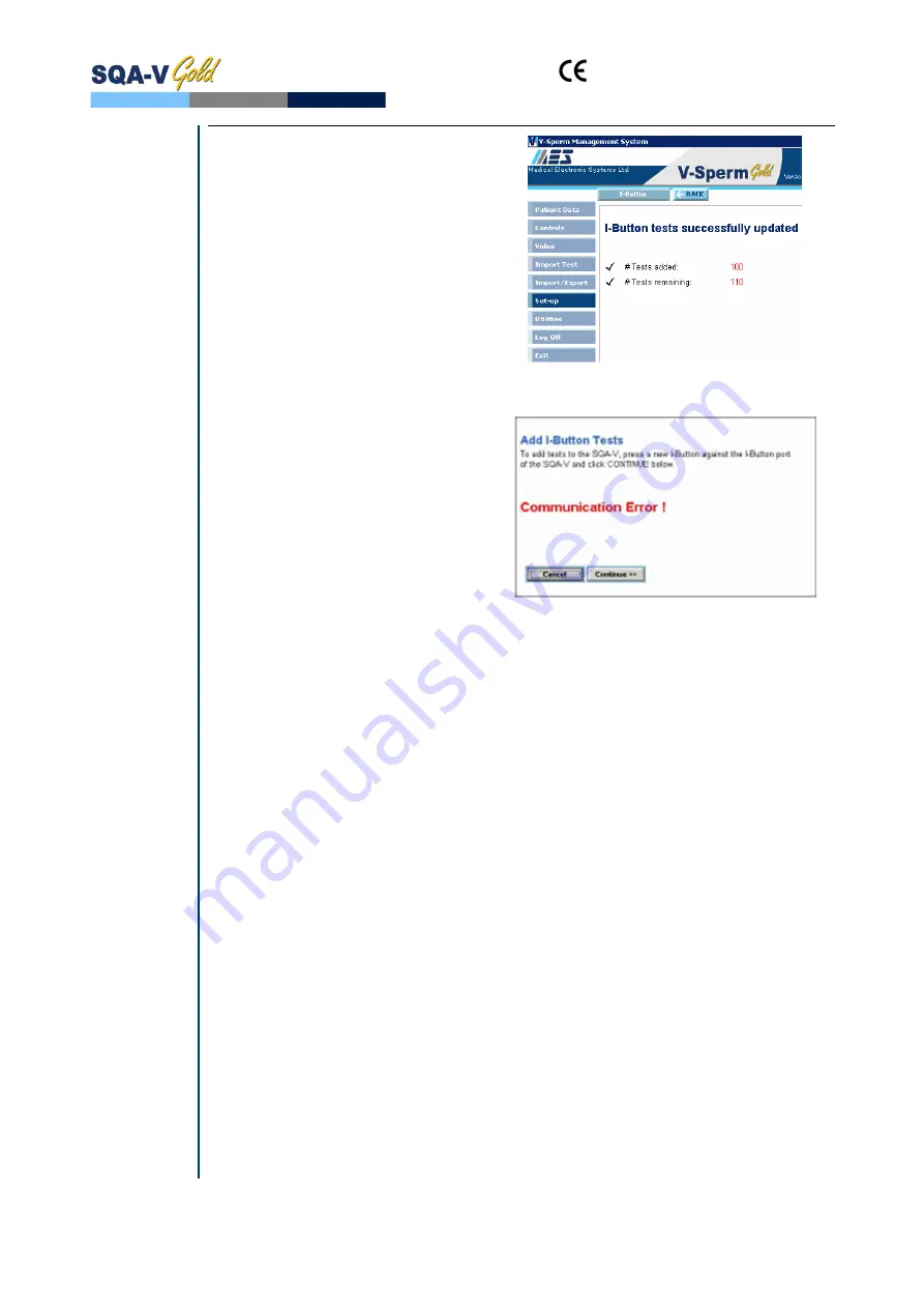
until you receive the message:  

I-Button Tests successfully 
updated

 (see Fig. 4).


Figure 4:

 Success Message 

Troubleshooting Errors 

Problem description

: I-Button 

Tests are not loading from the I-
Button after repeated attempts and 
an error message is displayed on the 
V-Sperm screen (see Figure 5) 

Explanation of the failure

: There is 

an intermittent I-button 
communication failure between the 
SQA-V and the computer in some 
cases. 


Figure 5:

  Error Message 

Troubleshooting Instructions 

1.


Click 

CONTINUE

 again if the I-button it doesn’t load tests and you receive a 

communication error. 

2.


If you still receive a 

Communication Error

 check the following:  


Is the I- button properly located (fully inserted) inside the port? 


Is every step being followed exactly as explained in the I-button 
loading procedure?  


Is a NEW I-button card being used? 

3.   Is the SQA-V connected (via an RS232) to your V-Sperm Computer?   (To test 

this- try importing your patient data…does this work?) 

4.


If you answered “Yes” to all of these questions, follow these instructions:   


Turn off the power on the SQA-V (from the back) 


While holding the SERVICE button of the SQA-V, turn the power 
switch back on 


You should now have a blank screen (sometimes with garbled lines) 


Immediately turn off the power again. 

5.


Finally, turn on the power and follow the “I-button loading instructions” again 
(section 1- section 6 above). 


Содержание SQA-V

Страница 1: ...and SQA V S e r v i c e M a n u a l V e r s i o n 2 4 8 2 4 9 2 6 0 Catalog 7501 Rev Dec 2019...

Страница 2: ...roubleshooting Overview 13 SECTION VIII Technical Support and Part Replacement Instructions Opening the SQA V 13 Closing the SQA V 14 Printer Thermal 14 Printer Impact 15 Keypad 15 Power Supply PSU 16...

Страница 3: ...and SQA V Service Manual Dec_2019 3 Communication Error 40 SECTION X Appendixes Cleaning Instructions 41 Loading I Button Tests 42 I Button troubleshooting 43 Power Supply Troubleshooting Flowchart 44...

Страница 4: ...perm ejaculate FUNC SPERM M Motile Sperm Concentration MSC M ml Total Morphologically Normal Sperm ejaculate MORPH NORM SPERM M Progressively Motile Sperm Concentration PMSC M ml Postvasectomy Motile...

Страница 5: ...mm section of the capillary by analyzing light modulations caused by sperm motion Step 4 This information is then digitized and routed to the microprocessor that applies algorithms to extract the req...

Страница 6: ...cus knob Display s Operational LCD screen with white backlight resolution 240 x 128 pixels Video LCD screen 4 diagonal resolution 960 x 240 pixels Use monitor On Off key on the keypad to independently...

Страница 7: ...photometer channel input signal Modulated 1 kHz analog up to 5V Quality Control Internal Electronic Self Test and Auto Calibration External Counts can be run on the SQA V automated and visualization s...

Страница 8: ...ions Operate the SQA V away from devices that may cause electronic noise cell phones or other devices causing vibrations such as centrifuges Turn system OFF at the rear panel when not in use for exten...

Страница 9: ...eld Use the ESC button to return to the previous screen or field Rear Panel Side Panel The side panel has an I Button port with clip in newer SQA V s starting with Serial Number 1333 Refer to the Appe...

Страница 10: ...alization Compartment Visualization Compartment Cover Measurement Compartment Focus control knob Schematic of the SQA V 1 5 to 1 8 VDC 5 VDC 5 VDC 12 VDC 3 VDC 12 VDC 12 VDC 2 VDC AC 100 230 V 50 60 H...

Страница 11: ...ion Slide Adaptor For use with a standard laboratory slide 76 x 25 6 mm and 22 x 22 mm cover slip in the visualization compartment of the SQA V to visually assess semen samples Cleaning Kit Daily clea...

Страница 12: ...d ranges Prior to testing a sample Auto calibration verification Reference values are read again The concentration and motility parameters are measured without a testing capillary System noise Measure...

Страница 13: ...V without voiding the warranty SECTION VII Troubleshooting Overview The following sections describe how to troubleshoot and repair potential problems that may occur with the SQA V Theses section will...

Страница 14: ...heck the cable connected between the printer and the main board location J3 and verify that is not damaged or disconnected If the cable is O K but printer is not working please proceed to printer repl...

Страница 15: ...ne Reconnect the cable to the printer and main board location J3 Attach the printer to the SQA V rear panel Close the SQA V according to the instructions from Closing the SQA V section above Keypad 5...

Страница 16: ...the Appendix section for instructions on how to address power supply problems 6 Power Supply Unit PSU ISSUE The main switch is ON but the power indicator does not light up and the fan is not working C...

Страница 17: ...ement of the Power Supply Unit ISSUE The power supply and or cables are not working PLEASE NOTE The instructions depend on the SERIAL NUMBER SN of the SQA V SN 1329 and below follow the instructions i...

Страница 18: ...onnector location CN1 Output connector location CN2 4 Using a 1 5 Philips screwdriver open four screws holding the faulty PSU 5 Replace the faulty PSU 6 Secure the new PSU to the rear panel using the...

Страница 19: ...r SQA V of SN 1330 and above use part V H 00575 00 Note When replacing the fan do not change the direction of airflow Install the new fan in the same direction and orientation as a replaced fan 1 Open...

Страница 20: ...CD screen Using a Phillips screwdriver remove the two screws that secure the faulty inverter board Replace the faulty inverter board with a new one and secure it with the two screws Re connect the cab...

Страница 21: ...h a new one and secure it with the four screws 6 Reconnect the data flat cable to new Operation monitor 7 Reconnect backlight power cable to Inverter board location J2 SECTION 2 SN 2229 and above Note...

Страница 22: ...orientation If data flat cable appears damaged in any way it should be replaced Item P N KHD 908 000858 4 If replacing the cable will not resolve the issue replace the processor on the main board see...

Страница 23: ...onitor above 7 If the problem persists with the new screen perform an MBOB replacement OR send the SQA back to the manufacturer MES for a repair RMA SECTION 3 Replacing the SQA V processor Instruction...

Страница 24: ...ocessor according to the following directions Align the dot which is marked on the processor with the Arrow mark on the processor socket see the figure to the right 5 Slightly press the center of the...

Страница 25: ...the SQA V and disconnect the optical assembly from the front panel four screws Disconnect the focus knob from the optical assembly by unscrewing three screws Remove the old focus knob Insert the new f...

Страница 26: ...he light source can be seen from the bottom of the LED house If no light can be seen please check the Illumination settings of SQA V 2 Illumination setting can be adjusted using designated buttons on...

Страница 27: ...st the video settings in V Sperm Go to VIDEO Real Time Video Settings Check to make sure the Brightness and Contrast setting are adjusted to achieve optimal image Check the external cables connecting...

Страница 28: ...of this manual If the problem persists after replacing the cable contact MES support 5 The image on the SQA V is frozen or stuck This type of problem can only occur in old systems with SN below 1318 I...

Страница 29: ...ng the two plastic clips push the internal video cable connector inside to release it 8 Gently lay the optical assembly on its rear section 9 Move the internal video cable aside and make sure nothing...

Страница 30: ...e lid fig 2 Do not start this procedure unless you have this track Contact MES if you need a FALSE TRACK 5 Unscrew the 2 screws holding DC Motor and remove it fig 3 and 4 6 Disconnect the internal vid...

Страница 31: ...ns for CCD cleaning but this time do not remove the dust sleeve 2 Using a Phillips screwdriver remove the four screws holding the camera PCB 3 Replace the defective CCD camera with a new one 4 Fasten...

Страница 32: ...dvised Only an experienced and licensed electrical technician or electrician should perform this repair How to check the Surge Protector Turn off the power and unplug the power cord from the inlet on...

Страница 33: ...located on the front face of the surge protector and verify that the surface inside the windows is green If at least one of the surfaces inside the windows is not green replace the surge protector Ho...

Страница 34: ...pillary sensor is defective and must be replaced follow the instructions in next section If the SELF TEST keeps failing while the values of Conc 1 Conc 2 and Conc 3 are ZERO call technical support for...

Страница 35: ...l Board to the LED Board were damaged and therefore require replacement Note The following instructions for replacing the Optical Board cables are applicable only for devices where aforementioned cabl...

Страница 36: ...Part V M00571 00 Issue A Visualization System Upgrade is available for purchase and can be easily installed on existing systems The upgrade consists of 3 components 1 Improved Visualization LED Housin...

Страница 37: ...e the Focus knob See section 13 in this manual for detailed instructions Stage 4 Close the SQA V Re connect the optical assembly to the front panel Make sure to screw back all 4 screws Close the back...

Страница 38: ...onic noise cell phones etc Clean measurement compartment refer to Appendix Reboot the SQA V without a testing capillary in the chamber Turn the system OFF then back ON at the main switch on the rear p...

Страница 39: ...ration Out of Range A message will appear indicating that the tests results for SPERM CONC and or MSC are beyond the dynamic range established by the manufacturer for testing This message will appear...

Страница 40: ...is activated but no more tests remain in the SQA V Insert a new I Button 7 Communication error A communication error may occur in one of the following cases Defective wire connection The cable that c...

Страница 41: ...and SQA V Service Manual Dec_2019 41 Appendix 1 SQA Cleaning Instructions SECTION X Appendixes...

Страница 42: ...button port of the SQA The back of the card instructions side should be facing up so that the clip touches the I button through the round hole at the back of the card See Fig 1 The I button should be...

Страница 43: ...k CONTINUE again if the I button it doesn t load tests and you receive a communication error 2 If you still receive a Communication Error check the following Is the I button properly located fully ins...

Страница 44: ...solved Yes Yes Yes Yes End of troubleshooting Not Not Not Not Voltage is OK Check the input voltage of PSU see p 16 Not OK Not OK Not OK Not OK Replace the power inlet see p 19 OK OK OK OK Check the...

Отзывы: