


and
SQA-V
Service Manual Dec_2019
35
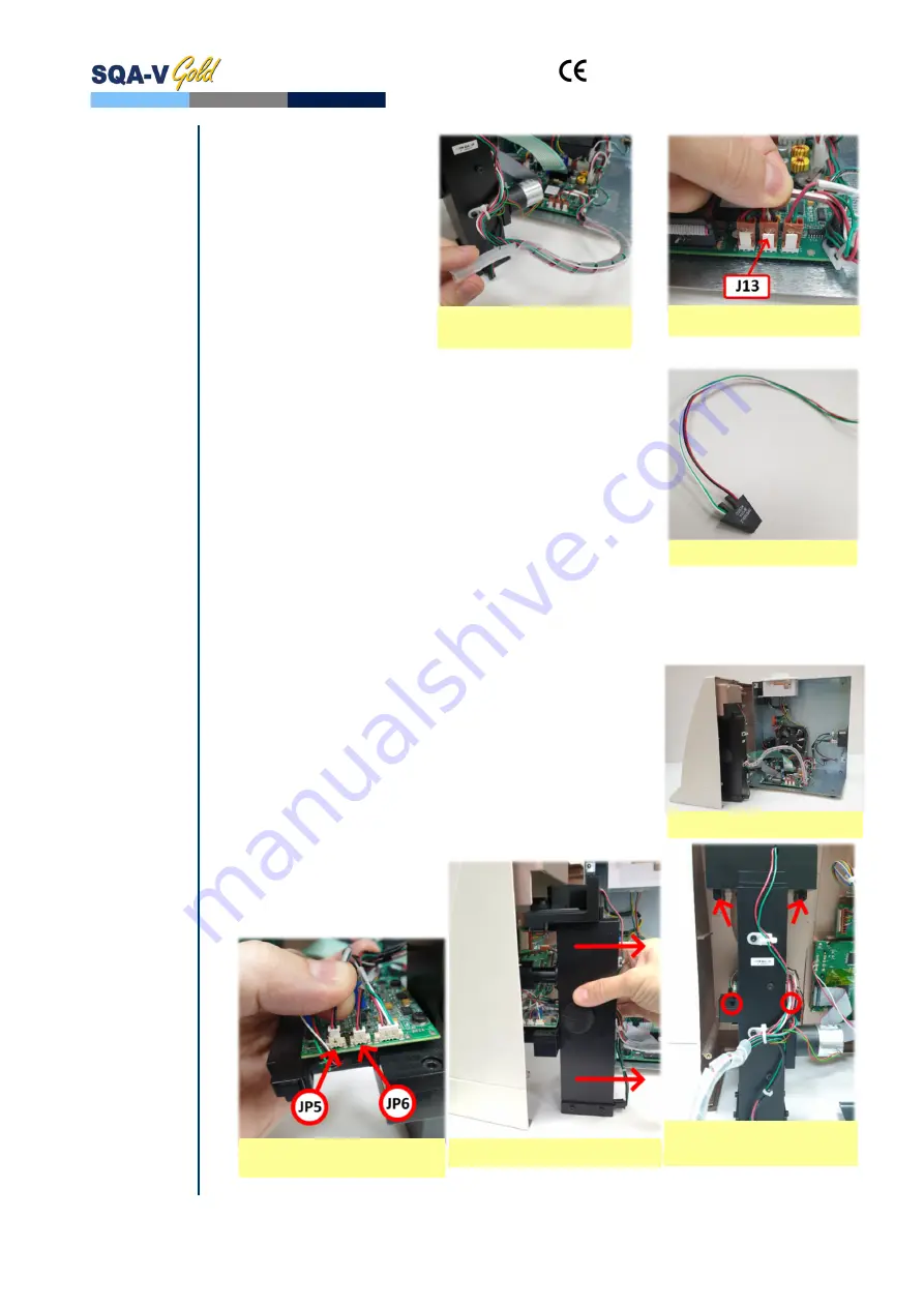
Unwind the white plastic
cable wrap that holds
the capillary sensor and
other cables
Unplug the cable
connector from its
location on the main
board- J13 and remove
the damaged capillary
sensor from the optical
block
Install a new capillary sensor harness on the optical
block and fasten it using the screw
Re-attach the cable to the cable bundle, fasten the
cables using the white plastic cable wrap
Connect the cable connector to its designated location on
the Motherboard - J13
Attach the optical column to the front panel of the SQA-V
using the original 4 screws
Attach back the front panel to the rear panel using a #2
Philips screwdriver
Optical
Board to LED
Board cables
23.
Optical Board to LEDs Board Cables - Replacement (Part#: KHD-908-000689)
Issue:
The noise level of the SQA-V (Parameter #17) is higher than 3. Probably the
cables connecting the Optical Board to the LED Board were damaged and therefore
require replacement
Note:
The following
instructions for
replacing the
Optical Board
cables are
applicable only
for devices
where
aforementioned
cables are
joined with the
boards by
means of
connectors.
For those
devices where
the Optical
Board cables are
joined with the
boards using
soldering
method the
following
instructions are
not applicable!
Please contact
the MES
customer
support team
for appropriate
solution.
Turn off the power and unplug the power cord from the
inlet on rear panel of SQA-V. Using a #2 Philips
screwdriver open the SQA-V by unscrewing four screws
from the rear panel
Using a #2.5 Allen key remove four screws connecting
the optical assembly to the front panel of the SQA-V (see
the pictures below)
Pull the optical assembly to remove it from the front
panel
Disconnect the damaged
cables from JP5 and JP6
connectors located on the
Optical board
Unwind the Plastic
Cable Wrap
Unplug the connector
Capillary Sensor
Disconnect the optical
assembly
Open the SQA-V
Pull the optical assembly
Disconnect the JP5 and
JP6


