


and
SQA-V
Service Manual Dec_2019
20
Operation
Monitor
10.
Operation Monitor - ISSUE #1:
LCD Screen (P/N: V-MA-00615-00)
The SQA-V is ON, power indication LED is functioning and the fan is working, but the LCD
screen (Operation Monitor) is not illuminated although data is displayed on the screen.
PLEASE NOTE: The instructions depend on the SERIAL NUMBER (SN#) of the SQA-V
SN# 2228 and below – follow the instructions in SECTION 1
SN# 2229 and above – follow the instructions in SECTION 2
SECTION 1: SN
#2228 and
below
Note:
Turn off the SQA-V
and disconnect the
power cord from
the back of the
device before
opening the SQA-V.
WARNING:
DO NOT TOUCH the
backlight lamp and
inverter board while
SQA-V is on! There
is a risk of HIGH
VOLTAGE shock!
1.
Open the SQA-V
2.
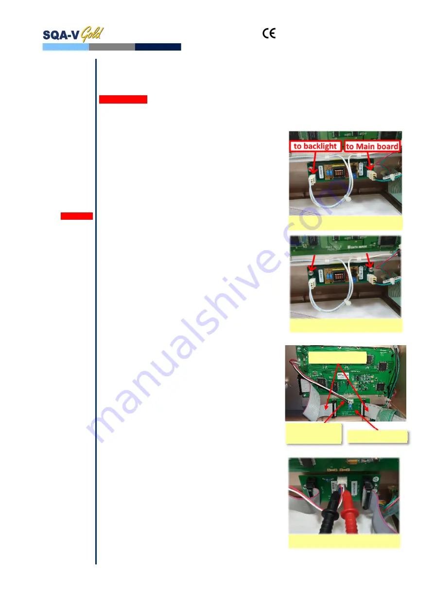
Turn on the SQA-V and check the input and
output cables of the inverter board: verify they
are connected properly and the connection is not
loose
3.
Check the voltage on purple wire of PSU output
connector and verify that it is within the range
(refer to Power Supply Unit section, paragraph
#6). If the measured voltage is OK but the
screen doesn’t light up, replace the faulty
inverter board (Item#AS-9084111):
Turn the SQA-V off and disconnect the
cables connecting the inverter board to the
main board and LCD screen
Using a Phillips screwdriver, remove the two
screws that secure the faulty inverter board
Replace the faulty inverter board with a
new one and secure it with the two screws
Re-connect the cables of the inverter board
If the problem persists, contact MES Customer
Support.
SECTION 2: SN
#2229 and
above
NOTE:
Turn off the SQA-V
and disconnect the
power cord from
the back of the
device before
opening the SQA-V.
1.
Open the SQA-V.
2.
Turn on the SQA-V and check the input and
output cables of the Backlight PCB: verify they
are connected properly and the connection is not
loose
3.
Using multimeter check the voltage on J3
connector of Backlight PCB. If the supplied
voltage is not +3.5V±0.1 replace the Backlight
PCB:
Turn the SQA-V off and disconnect the data
cables connecting the Backlight PCB to the
LCD screen and to the mother board
Disconnect the backlight power cable
Using a Phillips screwdriver, remove the two
screws that secure the faulty Backlight PCB
Replace the Backlight PCB with a new one
and secure it back with two screws
Re-connect all the cables to the new
Backlight PCB
4.
If the measured voltage is +3.5V±0.1 – replace
the Operation monitor (refer to section below for
detailed instructions)
5.
If the problem persists after replacing of
Backlight PCB and/or Operational monitor,
contact MES Customer Support
Backlight PCB
Backlight
power cable
Data Cables
Disconnect both cables
Remove both screws
Check voltage on J3 connector


