4 - COMMANDS AND INSTRUMENTS
4 - 21
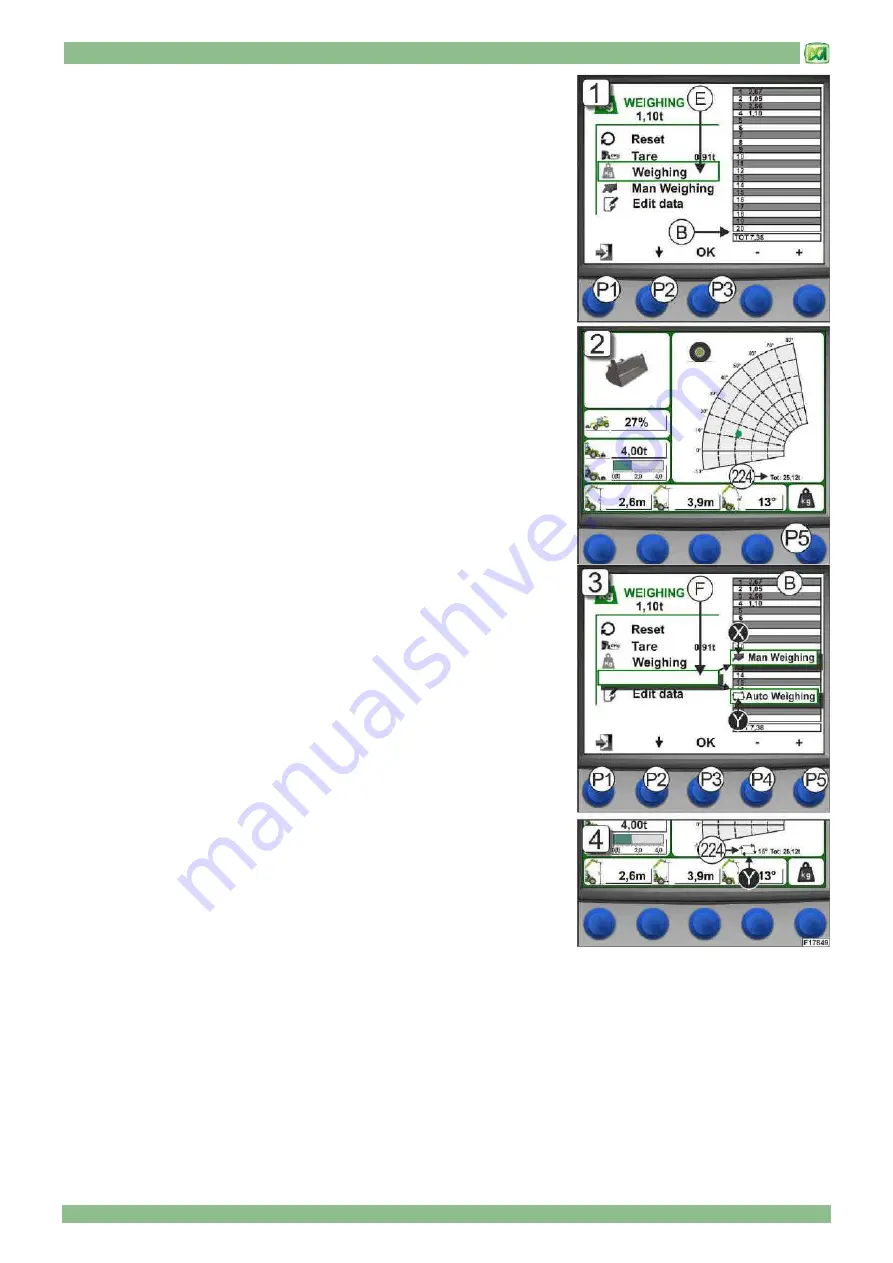
4) MANUAL WEIGHING (E)
Use this command to weigh the load lifted by the attachment manually. The data
measured by the system is displayed in Table "B" starting from box n. 1 through
to box n. 20. When there are more than 20 weighing operations, all values scroll
upwards and more recent figures will always be displayed at the bottom of the
table. The total shown at the bottom of Table "B" is always the sum of all
weighing operations, including those that are off-screen.
The manual weighing command is performed from the weighing screen using the
button (P2), selecting "WEIGHING" and then confirming by pressing the button
(P3). Audible confirmation is given that the weight has been read and the system
stores the result in Table "B".
To obtain the sum of all weighing operations performed, refer to the figure next to
the wording "TOT" at the bottom of the table; this total increases up to a
maximum of 9999,99 t. (Fig.1)
Press button (P1) to return to the main screen
It is also possible to perform a manual weighing operation even from the main
screen by pressing the OK button (P5); audible confirmation is given that the
weight has been read and the system stores the result. The main screen also
has the total for weighing operations performed and the value is given
underneath the load graph in field (224). Manual readout of weight from the main
screen can only be performed if "MAN WEIGHING" was previously selected in
the weighing screen. (Fig.2)
5) WEIGHING MODE (F)
This command is used to set the weighing readout mode:
1) MANUAL
2) AUTOMATIC
If manual weighing is set, the symbol "X" and the item "MAN WEIGHING"
appears; if automatic mode is set, the symbol "Y" and the item "AUTO
WEIGHING” appears. To perform manual weighing, refer to the instructions
provided in the previous item (MANUAL WEIGHING "E").while for automatic
weighing refer to the following instructions.
Move around the weighing screen using button (P2) and select the item "AUTO
WEIGHING"; then press button (P3) to confirm. It is now possible to set a lifting
angle for the telescopic boom beyond which the system automatically performs a
weighing operation. This angle must be set using buttons (P4, decrease) and
(P5, increase) and must be between 0° and 70°. Having set these functions,
press button (P1) and return to the MAIN MENU since automatic weighing does
not work in the WEIGHING MENU. (Fig.3)
In order to confirm that the system has been set correctly in automatic mode, the
main screen displays in field (224) the symbol "Y" and the value (in degrees) of
the angle chosen.
In this condition, every time the telescopic boom is lifted beyond this angle, the
system automatically weighs the load (with audible signal) and stores the value
in Table "B". The sum of weighing operations is always given in the main screen, under the load chart next to the wording
"TOT". (Fig.4)
To perform a new automatic weighing operation, lower the telescopic boom by 5° less than the value of the angle set
beforehand; if this is not the case, when the telescopic boom is lifted again, the system will not perform an automatic weighing
operation.
Содержание PANORAMIC
Страница 20: ...2 MACHINE TECHNICAL INFORMATION 2 9 only for models P60 10EE P72 10EE...
Страница 22: ...2 MACHINE TECHNICAL INFORMATION 2 11 only for models P38 12 P38 13 P38 14 P40 17 P38 13EE P40 17EE...
Страница 27: ...2 MACHINE TECHNICAL INFORMATION 2 16 DIMENSIONS P37 12 PLUS DIMENSIONS P38 12 PLUS P38 12...
Страница 28: ...2 MACHINE TECHNICAL INFORMATION 2 17 DIMENSIONS P38 13 PLUS P38 13 P38 13EE DIMENSIONS P38 14 PLUS P38 14...
Страница 29: ...2 MACHINE TECHNICAL INFORMATION 2 18 DIMENSIONS P40 9 PLUS DIMENSIONS P40 17 PLUS P40 17 P40 17EE...
Страница 30: ...2 MACHINE TECHNICAL INFORMATION 2 19 DIMENSIONS P60 10 P60 10EE DIMENSIONS P72 10 P72 10EE...
Страница 34: ...2 MACHINE TECHNICAL INFORMATION 2 23 MACHINE WITH STABILISERS LIFTING A LOAD USE CONDITIONS TRANSPORTING A LOAD...
Страница 35: ...2 MACHINE TECHNICAL INFORMATION 2 24 LIFTING A LOAD...
Страница 44: ...3 STICKERS WITH CONTROL DESCRIPTIONS LEAFLETS IN THE CAB 3 3 only for models P60 10EE P72 10EE...
Страница 48: ...3 STICKERS WITH CONTROL DESCRIPTIONS LEAFLETS IN THE CAB 3 7 OUTSIDE CAB STICKERS P40 17 PLUS P40 17 P40 17EE...
Страница 49: ...3 STICKERS WITH CONTROL DESCRIPTIONS LEAFLETS IN THE CAB 3 8...
Страница 51: ...3 STICKERS WITH CONTROL DESCRIPTIONS LEAFLETS IN THE CAB 3 10...
Страница 52: ...3 STICKERS WITH CONTROL DESCRIPTIONS LEAFLETS IN THE CAB 3 11 P37 12 PLUS P40 9 PLUS...
Страница 53: ...3 STICKERS WITH CONTROL DESCRIPTIONS LEAFLETS IN THE CAB 3 12...
Страница 54: ...3 STICKERS WITH CONTROL DESCRIPTIONS LEAFLETS IN THE CAB 3 13 P60 10 P72 10 P60 10EE P72 10EE...
Страница 55: ...3 STICKERS WITH CONTROL DESCRIPTIONS LEAFLETS IN THE CAB 3 14 END OF SECTION...
Страница 138: ......
Страница 185: ......
Страница 189: ...9 HYDRAULIC CIRCUIT DIAGRAMS 9 4 valid for models P38 12 P38 13 P38 14 P40 17 P38 13EE P40 17EE P60 10EE P72 10EE...
Страница 191: ...9 HYDRAULIC CIRCUIT DIAGRAMS 9 6 HYDRAULIC SYSTEM DIAGRAM valid for models P38 12PLUS P38 13PLUS P38 14PLUS P40 17PLUS...
Страница 193: ...9 HYDRAULIC CIRCUIT DIAGRAMS 9 8 valid for models P37 12 PLUS P40 9 PLUS P60 10 P72 10 P60 10EE P72 10EE...
Страница 195: ...9 HYDRAULIC CIRCUIT DIAGRAMS 9 10 valid for models P38 12 P38 13 P38 14 P40 17 P38 13EE P40 17EE...
Страница 197: ...10 ELECTRICAL SYSTEM 10 1 CONTENTS GENERAL FEATURES 2 BATTERY 2 FUSES 3 END OF SECTION 4...


