6 - ORDINARY MAINTENANCE
6 - 26
EVERY 1500 HOURS OR EVERY 18 MONTHS
• HYDROSTATIC TRANSMISSION SYSTEM
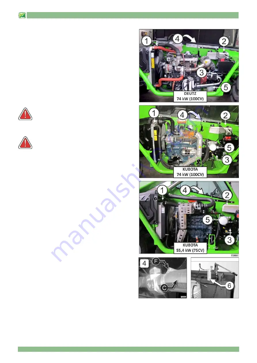
Replace the oil from the hydrostatic transmission system
1)
Radiator
2)
Tank
3)
Hydrostatic pump
4)
Hydrostatic motor
5)
Hydrostatic transmission filter
6)
Hand pump
The total capacity of the system is 12 litres
WARNING! Use only hydrostatic oil shown in
paragraph FUEL AND LUBRICANTS ..
OIL REPLACEMENT
WARNING! Oil change in the hydrostatic transmission
must be performed by skilled and qualified personnel.
-
unscrew the caps of the radiator (1) and hydrostatic oil tank (2)
-
remove the filter (5) and drain the oil into a container; to
perform this operation, proceed in the manner described in the
Filter Replacement Paragraph “EVERY 500 HOURS”
-
disconnect pipe "F" located beneath the hydrostatic motor (4),
then drain the oil from the system into a container.
-
once the oil has been completely drained, reconnect piping "F"
in its correct position
-
install a new filter (5) for the hydrostatic transmission
-
The system must be filed with specific hydraulic oil, filtered at
10-micron and supplied at a pressure of about 2.5 bar.
-
For this purpose use a hand pump "M" as shown in the photo
(6). Pour the oil into the hydrostatic pump through pressure
inlet (fitting M16x2) until the tank is filled
-
close radiator cap (1)
-
close cap (2) of the tank
-
Remove the hand pump from the pressure connection and
close the cap
The system must be bled after filling; follow the instructions below:
-
closing the bonnet, get in the cab and start the engine
-
leave the engine running for about 2 minutes
-
switch off the engine
-
wait 2 minutes to allow the air to bleed completely from the
system.
-
open the bonnet and check that the oil level in the tank is
between the MIN and MAX marks. If not top up the level with
the specific oil (see paragraph FUEL AND LUBRICANTS in
this chapter).
Repeat this procedure until, having left the engine running for about 2 minutes, the oil level is within the MIN and MAX marks
on the tank.
Содержание PANORAMIC
Страница 20: ...2 MACHINE TECHNICAL INFORMATION 2 9 only for models P60 10EE P72 10EE...
Страница 22: ...2 MACHINE TECHNICAL INFORMATION 2 11 only for models P38 12 P38 13 P38 14 P40 17 P38 13EE P40 17EE...
Страница 27: ...2 MACHINE TECHNICAL INFORMATION 2 16 DIMENSIONS P37 12 PLUS DIMENSIONS P38 12 PLUS P38 12...
Страница 28: ...2 MACHINE TECHNICAL INFORMATION 2 17 DIMENSIONS P38 13 PLUS P38 13 P38 13EE DIMENSIONS P38 14 PLUS P38 14...
Страница 29: ...2 MACHINE TECHNICAL INFORMATION 2 18 DIMENSIONS P40 9 PLUS DIMENSIONS P40 17 PLUS P40 17 P40 17EE...
Страница 30: ...2 MACHINE TECHNICAL INFORMATION 2 19 DIMENSIONS P60 10 P60 10EE DIMENSIONS P72 10 P72 10EE...
Страница 34: ...2 MACHINE TECHNICAL INFORMATION 2 23 MACHINE WITH STABILISERS LIFTING A LOAD USE CONDITIONS TRANSPORTING A LOAD...
Страница 35: ...2 MACHINE TECHNICAL INFORMATION 2 24 LIFTING A LOAD...
Страница 44: ...3 STICKERS WITH CONTROL DESCRIPTIONS LEAFLETS IN THE CAB 3 3 only for models P60 10EE P72 10EE...
Страница 48: ...3 STICKERS WITH CONTROL DESCRIPTIONS LEAFLETS IN THE CAB 3 7 OUTSIDE CAB STICKERS P40 17 PLUS P40 17 P40 17EE...
Страница 49: ...3 STICKERS WITH CONTROL DESCRIPTIONS LEAFLETS IN THE CAB 3 8...
Страница 51: ...3 STICKERS WITH CONTROL DESCRIPTIONS LEAFLETS IN THE CAB 3 10...
Страница 52: ...3 STICKERS WITH CONTROL DESCRIPTIONS LEAFLETS IN THE CAB 3 11 P37 12 PLUS P40 9 PLUS...
Страница 53: ...3 STICKERS WITH CONTROL DESCRIPTIONS LEAFLETS IN THE CAB 3 12...
Страница 54: ...3 STICKERS WITH CONTROL DESCRIPTIONS LEAFLETS IN THE CAB 3 13 P60 10 P72 10 P60 10EE P72 10EE...
Страница 55: ...3 STICKERS WITH CONTROL DESCRIPTIONS LEAFLETS IN THE CAB 3 14 END OF SECTION...
Страница 138: ......
Страница 185: ......
Страница 189: ...9 HYDRAULIC CIRCUIT DIAGRAMS 9 4 valid for models P38 12 P38 13 P38 14 P40 17 P38 13EE P40 17EE P60 10EE P72 10EE...
Страница 191: ...9 HYDRAULIC CIRCUIT DIAGRAMS 9 6 HYDRAULIC SYSTEM DIAGRAM valid for models P38 12PLUS P38 13PLUS P38 14PLUS P40 17PLUS...
Страница 193: ...9 HYDRAULIC CIRCUIT DIAGRAMS 9 8 valid for models P37 12 PLUS P40 9 PLUS P60 10 P72 10 P60 10EE P72 10EE...
Страница 195: ...9 HYDRAULIC CIRCUIT DIAGRAMS 9 10 valid for models P38 12 P38 13 P38 14 P40 17 P38 13EE P40 17EE...
Страница 197: ...10 ELECTRICAL SYSTEM 10 1 CONTENTS GENERAL FEATURES 2 BATTERY 2 FUSES 3 END OF SECTION 4...


