


6 - ORDINARY MAINTENANCE
6 - 3
-
if you need to carry out maintenance operations underneath the machine, use either a pit or an auto lift having proper
features. For the total weight of the machine please refer to the identification plate applied on the outside of the cab.
-
if you need to raise the telescopic boom to carry out maintenance operations, equip the working area with external supports
which can support the telescopic boom and prevent it from being lowered accidentally. For this purpose connect a sling to a
suitable hoisting device having a minimum load capacity of 2,000 kg. (4,400 lb)
-
if you need to lift the machine from the ground to carry out maintenance operations, use a suitable lifting device which
complies with safety rules; the coupling points on the machine are shown by a yellow triangular sticker.
-
before carrying out any maintenance operations on either a tire or a rim, deflate the tire completely.
-
while inflating tires, never stand in front of the tire sidewall; place yourself sideways.
-
never make welds on the rim if the wheel is still mounted on the machine, since this may lead to either an explosion or a
fire.
-
avoid any prolonged, repeated contact between your skin and fuels, lubricants or other fluids, since this may cause skin
disorders or other syndromes.
-
never ingest fuels, lubricants, or other fluids.
-
during filter cleaning or replacement, make sure that the room is properly ventilated, in order to prevent toxic fumes from
accumulating.
-
never make welds in enclosed rooms which are not properly ventilated.
-
never make welds on painted surfaces. Remove the paint with suitable products first, then wash the surfaces and let them
dry.
-
be careful when removing caps from tanks, radiators, or cylinders: turn them cautiously to relieve any residual pressure.
-
stay out of the way during draining operations, and always wear protection goggles. Slowly unscrew the draining screw by a
few turns to let either the condensate or the fluid come out.
-
relieve pressure from circuits before carrying out maintenance operations.
-
never try to identify leaks of pressurized fluids with your bare hands.
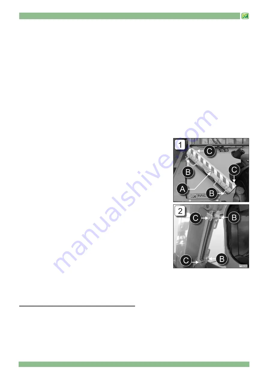
MECHANICAL RETAINER FOR THE LIFT CYLINDER
If you need to carry out maintenance work on your machine with the boom raised,
first you have to apply mechanical retainer 'A' supplied with your machine.
When in its home position, this retainer is placed on the front left mudguard.
To remove the mechanical retainer from its home position carry out the following
operations (picture 1)
- remove split pins 'B'
- remove pins 'C'
- pick up mechanical retainer 'A' from its handles
To apply the mechanical retainer on the lift cylinder, follow the instructions below:
- fully raise the telescopic boom of your machine
- place mechanical retainer 'A' around the lift cylinder, as shown in picture 2
- insert fastening pins 'C'
- insert split pins 'B'
After completing all maintenance operations, put the mechanical retainer back to
its home position by carrying out the operations above in reversed order.
FUEL AND LUBRICANTS
Please follow these descriptions in order to know type of fuel, oils and greases to be used on your machine.
• DIESEL FUEL
For further details consult the manual of the relative engine.
- FUEL STORAGE
Carefully observe the following rules to correctly store the fuel:
-
Store the diesel fuel in clean containers, away from direct sunlight and in a protected area.
-
Before refuelling the machine, eliminate any dirt, water or sediment in the deposit tanks, as these may obstruct filters, the
injection pump or injectors. This is particularly needed if diesel is stored for a long period of time.
-
Do not use antifreeze to extract water from diesel
-
Do not rely only on the pre-filter found on the machine to completely eliminate water from the diesel fuel.
Содержание P25.6
Страница 2: ...04 2017 PUBLICATION DATE...
Страница 4: ......
Страница 6: ......
Страница 21: ...2 MACHINE TECHNICAL SPECIFICATIONS 2 9...
Страница 27: ...3 STICKERS WITH CONTROL DESCRIPTIONS LEAFLETS IN THE CABIN 3 3 STICKERS OF CONTROL PANEL P...
Страница 28: ...3 STICKERS WITH CONTROL DESCRIPTIONS LEAFLETS IN THE CABIN 3 4 OUTSIDE CAB STICKERS...
Страница 30: ......
Страница 60: ......
Страница 78: ......
Страница 90: ...6 ORDINARY MAINTENANCE 6 12...
Страница 114: ......
Страница 120: ......
Страница 137: ...9 HYDRAULIC CIRCUITS DIAGRAMS 9 1 INDEX HYDROSTATIC TRANSMISSION CIRCUIT 2 HYDRAULIC SYSTEM 4 END OF CHAPTER 5...
Страница 138: ...9 HYDRAULIC CIRCUITS DIAGRAMS 9 2 HYDROSTATIC TRANSMISSION CIRCUIT...
Страница 140: ...9 HYDRAULIC CIRCUITS DIAGRAMS 9 4 HYDRAULIC SYSTEM...
Страница 142: ......
Страница 143: ...10 ELECTRICAL SYSTEM 10 1 INDEX GENERAL FEATURES 2 BATTERY 2 FUSES 4 END OF CHAPTER 5...
Страница 148: ......
Страница 149: ...M2 M2 P256 AU 01 1...
Страница 150: ...M2 2 M2 P256 AU 01...
Страница 151: ...M2 M2 P256 AU 01 3...
Страница 152: ...M2 4 M2 P256 AU 01...
Страница 153: ...M2 M2 P256 AU 01 5...
Страница 154: ...M2 6 M2 P256 AU 01...
Страница 155: ...M2 M2 P256 AU 01 7...
Страница 156: ...M2 8 M2 P256 AU 01...
Страница 157: ...M2 M2 P256 AU 01 9...
Страница 158: ...M2 10 M2 P256 AU 01...
Страница 159: ...M2 M2 P256 AU 01 11...
Страница 160: ...M2 12 M2 P256 AU 01...
Страница 161: ...M2 M2 P256 AU 01 13...
Страница 162: ......
Страница 163: ...MODULE M3 ATTACHMENTS FOR MERLO ZM2 CARRIAGE...
Страница 164: ......
Страница 166: ......
Страница 172: ......
Страница 230: ...MODULE 3 SECTION 2 ATTACHMENTS 62 M M3 3 Z ZM M2 2 0 03 3 E EN N...
Страница 231: ...ATTACHMENTS FOR MERLO ZM2 CARRIAGE M3...
Страница 232: ......