Positioning the motor and plinth.
Before preparing the plinth for use ensure that you have the correct
orientation and location for the motor.
No part of the motor or pinion should extend past the gate.
The motor plinth and all electronics should be located within the
propertyʼs boundaries.
The motor can be adjusted up and down and back and forth to some
degree however planning the location of your plinth and conduit exit will
save you time and effort.
Installing the base plate.
Where possible the base plate provided should be
installed into a concrete plinth.
The Base plate should be installed into a concrete plinth
of approximate 500mm x 500mm x 500mm for maximum
strength.
Ensure that a conduit is installed before adding the
concrete and that the exit point for the conduit is on the
correct side of the base plate in relation to the motor.
The plate has two recesses, ensure that the conduit
exits to the rear of the motor, this will facilitate the
passage of wire through the grommet located at the
base of the control box housing.
NOTE: For best results make sure the plinth
is level and has adequate drainage. Pooled
water around the base of the motor will
damage the gate motor.
200
2
1
5
12
4
0
6
0
2
8
3
0
27
0
m
m
75
m
m
160
160 mm
100
mm
180 mm
gate side
rear of motor
4
Installation
1.Turn key 180
2.Turn release mechanism 270
0
0
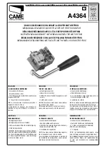
Manual release
In the case of a power failure or to move the gate freely
during installation the drive pinion must be disengaged.
To release the drive pinion.
• Turn the key 180 degrees to unlock
the release mechanism
• Turn the release mechanism 270
degrees to the right to release the
pinion.
NOTE:
The gate should move freely once the drive
pinion has been released.


