background image

P11 EXP 

Portable Digital Color Doppler Ultrasound System 

6-7

MENU 

F4 

F5 

Move the trackball fast forward to start playing the cine 

loop. Touch the trackball to stop the playback. 

Press the 

knob and the cine mode menu (right) 

will appear at the context menu area (refer to 

Figure 

2.4

). 

More cine mode operations are introduced in the fol- 

lowing subsections. 

6.4.1


C Map 

  C MAP 


Figure 6.3: 

CFM cine mode con- 

text menu 

Refer to 

Section 6.3.7 

for explanations of this function. To change the 

C MAP 

setting, 

•  press 

or 

to select 

C MAP

, turn the function knob to change the 

C MAP 

setting; 

• select 

C MAP 

from the context menu, turn the 

MENU 

knob to change the 

C  MAP

setting.

6.4.2


B Reject 

  B REJECT 

Refer to 

Section 6.3.11 

for explanations of this function. 

•  press 

setting; or 

to select 

B REJECT

, turn the function knob to change the 

B REJECT 

• select 

B REJECT 

from the context menu, turn the

REJECT 

setting.

knob to change the 

6.4.3


Flow Invert 

  FLOW INVERT 

Refer to 

Section 6.3.14 

for explanations and usage of this function. 

6.4.4


Cine Review 

  CINE REVIEW 

If the same patient has gone through the same diagnosis before, the saved images can be 

accessed conveniently from the cine mode menu. 

• Press 

to select 

CINE REVIEW 

• turn the function knob to select the cine image for review from a list of cine images.

• press the 

key to start reviewing the selected image. 

Remarks:

Press the 

FREEZE 

key to return to the real time scan immediately. 

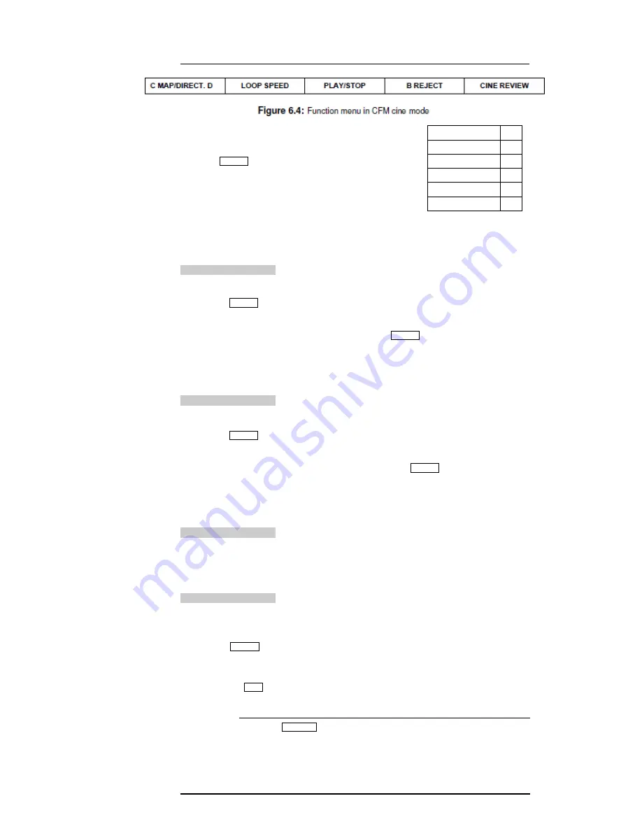
C MAP 

B REJECT 

254 

LOOP SPEED 

↔ 

START 

|← 

END 

→| 

FRAME BY FRAME 

.... 

F1 

MENU 

SET 

Содержание P11 EXP

Страница 1: ...User Manual P11 EXP Ultrasound System Version 1 1 ...

Страница 2: ... The manufacturer does not assume any liability arising out of any infringements of patents or other rights of third parties This manual is based on the maximum configuration and therefore some contents may not apply to your product This manual is subject to change without prior notice and legal obligation Manufacturer s Responsibility The manufacturer is responsible for the effects on safety reli...

Страница 3: ...ation which if not avoided could result in death or serious injury Indicates a potentially hazardous situation which if not avoided may result in malfunction or damage of the system NOTE Indicates precautions or recommendations that should be used in operating the system Indicates a potentially biological hazardous situation which if not avoided may result in disease transmission Boldface d Word I...

Страница 4: ...P11 EXP Portable Digital Color Doppler Ultrasound System 0 2 ...

Страница 5: ... 6 11 Environmental Protection 1 13 6 12 System Transportation 1 14 6 12 1 Moving the System 1 14 6 12 2 Transporting the System 1 14 7 System Specifications 2 1 7 1 Application and Contraindication 2 2 7 2 System Overview 2 2 7 3 Probes and Accessories 2 4 7 4 Physical Specifications 2 5 7 5 Concept of Operation 2 5 7 5 1 Screen Layout 2 5 7 5 2 Keyboard Layout 2 6 7 5 3 Keyboard Description 2 7 ...

Страница 6: ...dit 4 10 9 6 6 Define Quick Key 4 11 9 6 7 Load Default 4 12 9 6 8 DICOM Setting 4 14 10 B Mode 5 1 10 1 Starting B Mode 5 2 10 2 B Mode Image Information 5 2 10 3 Real Time B Mode Operation 5 3 10 3 1 B Mode Menus 5 3 10 3 2 ECG Optional 5 3 10 3 3 B Gain 5 4 10 3 4 Time Gain Compensation TGC 5 4 10 3 5 Depth 5 4 10 3 6 Focal Zones 5 5 10 3 7 Tissue Acoustic Characteristics 5 6 10 3 8 Dynamic Ran...

Страница 7: ...tion 6 2 6 3 1 CFM Menus 6 2 6 3 2 Adjust CFM Sample Box 6 3 6 3 3 Pulse Repetition Frequency 6 3 6 3 4 Wall Filter 6 3 5 CFM Gain 6 3 6 Persistence 6 3 7 Color Map 6 3 8 CFM Power 6 3 9 Baseline 6 3 10 Sector Width and Position 6 3 11 B Reject 6 3 12 CFM Frequency 6 3 13 Image Orientation Left Right 6 3 14 Flow Invert 6 3 15 Line Density 6 3 16 2D Refresh 6 4 CFM Cine Mode 6 4 1 C Map 6 4 2 B Rej...

Страница 8: ... TDI Sample Box 8 2 8 3 3 Pulse Repetition Frequency 8 3 8 3 4 Wall Filter 8 3 8 3 5 TDI Gain 8 3 8 3 6 Persistence 8 3 8 3 7 Color Map 8 4 8 3 8 TDI Power 8 4 8 3 9 Baseline 8 4 8 3 10 Sector Width and Position 8 4 8 3 11 B Reject 8 5 8 3 12 TDI Frequency 8 5 8 3 13 Image Orientation Left Right 8 5 8 3 14 Flow Invert 8 5 8 3 15 Line Density 8 5 8 3 16 2D Refresh 8 6 8 4 Cine Mode Operation 8 6 8 ...

Страница 9: ...er Frequency 10 5 10 2 9 Sweep Speed 10 5 10 2 10 Baseline 10 5 10 2 11 PW Power 10 6 10 2 12 Angle Correction 10 6 10 2 13 Dynamic Range DYN 10 6 10 2 14 Chroma 10 6 10 2 15 Video Invert 10 7 10 3 CW Mode Operation 10 7 10 3 1 Activation of CW Mode PW CW 10 7 10 3 2 CW Cursor Position 10 7 10 3 3 Flow Invert 10 8 10 3 4 Sweep Speed 10 8 10 3 5 CW Power 10 8 10 3 6 Dynamic Range DYN 10 8 10 3 7 Ch...

Страница 10: ...4 13 4 13 4 14 Probes 14 1 14 1 Probe 14 1 14 1 1 Available Probes 14 1 14 1 2 Probe Usage 14 1 14 1 3 Cleaning the Probe 14 2 14 1 4 Disinfecting or Sterilizing the Probe 14 2 14 1 5 Disinfecting and Sterilizing theProbe Cable 14 4 14 1 6 Storage and Transportation 14 5 15 System Maintenance 15 1 15 1 Manufacturer Responsibility 15 1 15 2 Cleaning the System 15 1 15 3 Maintenance Checks 15 2 15 4...

Страница 11: ...e the disconnection device In the event of a malfunction turn off the system immediately and inform the manu facturer or its designated agents The power cable of the system should only be connected to a grounded power socket Do not remove the ground cable for any reason Only connect this system either electronically or mechanically with devices that comply with the IEC60601 1 standard Recheck the ...

Страница 12: ...gh level disinfectants for use in processing reusable medical anddental devices onFDAwebsite That listcanbeconsulted to find agents that may be useful for probe disinfection Please refer to the following URL for FDA Cleared Sterilants and High Level Disinfectants http www fda gov MedicalDevices DeviceRegulationandGuidance ReprocessingofSingle UseDevices ucm133514 htm Do not knock or shake the syst...

Страница 13: ...ence of flammable anesthetics Type BF Applied Part Main switch OFF Main switch ON On Standby switch Footswitch Connector Protective earth ground Equipotentiality Alternating current Degree of IP protection Non ionizing electromagnetic radiation Manufacturer Date of manufacture Follow instructions for use Network Port USB Port ...

Страница 14: ...e for license renewal Auto quit ultrasound scan In order to protect the operator or the patient from accidentally receiving excessive acoustic energy the system automatically stops the real time scan no on screen messagewillbeprovided andreturnsthepreparationmodeiftherehasbeennouser activity for 30 minutes The user may resume the scan from the preparation mode No prerequisite action before another...

Страница 15: ...rasound outweigh the risks if any that may be present Heating Elevating tissue temperature during obstetrical examinations creates medical concerns At the embryo development stage the rise in temperature and the length of time exposed to heat combine to determine potential detrimental effects Exercise CAUTION particularly during Doppler Color exams The Thermal Index TI provides a statistical estim...

Страница 16: ...en moved to its maximum value 5 Maintain the shortest examination time necessary to produce a useful diagnostic result 6 Do not hold the probe in a fixed position for any longer than is necessary It should be removed from the patient whenever there is no need for real time imaging or spectral Doppler acquisition The freeze frame and Cine loop capabilities allow images to be reviewed and discussed ...

Страница 17: ...sole purpose of producing souvenir videos or photographs nor should their production involve increasing the exposure levels or extending the scan times beyond those needed for clinical purposes 12 Diagnostic ultrasound has the potential for both false positive and false negative results Misdiagnosis is far more dangerous than any effect that might result from the ultrasound exposure Therefore diag...

Страница 18: ...t a TI equal to 1 does not mean the temperature will rise 1 degree C It only means an increased potential for thermal effects can be expected as the TI increases A high index does not mean that bioeffects are occurring but only that the potential exists and there is no consideration in the TI for the scan duration so minimizing the overall scan time will reduce the potential for effects These oper...

Страница 19: ...1TIS Soft tissue Unscanned Large aperture 1cm Liver PW 2TIS Soft tissue Unscanned Small aperture 1cm Pencil probe 3TIS Soft tissue Scanned Evaluated at surface Breast color 4TIB Soft tissue and Scanned Soft tissue at surface Muscle color bone 5TIB Soft tissue and Unscanned Bone at focus Fetus head PW bone 6TIC Soft tissue and Unscanned Scanned Bone at surface Trans cranial bone Soft tissue Describ...

Страница 20: ...ing of the operating mode or if maximum TI is less than 1 0 for any setting of the operating mode For TI if the TIS and TIC are both greater than 1 0 the scanners need not be capable of displaying both indices simultaneously If the index falls below 0 4 no display is needed The display increments are no greater than 0 2 for index value less than one and no greater than 1 0 for index values greater...

Страница 21: ...maged Grounding Before connecting the power cable connect the attached ground protection cable to a specialized grounding device Note Please ensure that the power requirements are satisfied Only use powerlinesthatmeetthesystemguidelines failuretofollowthese procedures may result in system damage Voltage level may vary in different geographic locations Use onlythe powerbuttononthe side panel to tur...

Страница 22: ...urce which produces significant amount of heat such as fire and heater Do not charge or discharge the battery in direct sunlight Do not destroy or disassemble the battery Do not solder the battery This battery pack should only be used with the ultrasound system which it has been designed for Do not use the battery in strong electric field For more information about the AC adapter and the battery r...

Страница 23: ...to this ultrasound system must comply with the specified IEC standards IEC 60950 Information Technology Equipment Safety and IEC 60601 1 Medical electrical equipment Part 1 General requirements for basic safety and essential performance For cleaning disinfection and sterilization of accessories please follow the instruc tions provided by the manufacturers Installation and service of accessories sh...

Страница 24: ... power cord do not pull stretch or bend it excessively 5 Store the probes in their carrying cases or wrap them in soft cloth or foam to prevent damage 6 Store gel and other essential accessories in the appropriate storage cases 1 12 2 Transporting the System Use extra care when transporting the system in a vehicle After preparing the system as described above take the following additional PRECAUTI...

Страница 25: ...2 System Specifications Contents 2 1 Application and Contraindication 2 2 2 2 System Overview 2 2 2 3 Probes and Accessories 2 4 2 4 Physical Specifications 2 5 2 5 Concept of Operation 2 5 2 5 1 Screen Layout 2 5 2 5 2 Keyboard Layout 2 6 2 5 3 Keyboard Description 2 7 ...

Страница 26: ...raindication Application The device is a general purpose ultrasonic imaging instrument intended for use by a qualified physician Contraindication The system is not intended for OPHTHALMIC use or any use that causes the acoustic beam to pass through the eye 2 2 System Overview Front View ...

Страница 27: ...o 2 in Figure 2 1 and composite video 5 in Figure 2 2 output In order to use the composite video output make sure the S Video port is disconnected and connect the composite connector before the system startup In order to use the S Video output make sure the composite video output port is disconnected before the system startup Dust covers Some IO sockets are covered using dust covers To remove the ...

Страница 28: ...n Port 2 7 Equipotential point earth 3 Video Printer Controller Port 8 DC input 4 Foot Switch Socket 5 Composite Video Out 2 3 Probes and Accessories Supported Transducers see 14 1 1 Available Probes Standard System Configuration Main unit Footswitch Cable hook Standard accessories package AC Power cable Rating label of fuse Basic user manual Advanced user manual ...

Страница 29: ...ghlighted with a red triangle 2 4 Physical Specifications Net weight system alone without docking cart approximately 9 8kg LCD monitor 15 Dimensions with lid opened L W H 400mm 360mm 398mm 2 5 Concept of Operation 2 5 1 Screen Layout The user interface of the preparation mode is shown in Figure 2 3 Hospital name Figure 2 3 EXAM screen user interface of the preparation mode The user interface of th...

Страница 30: ...4 Probe 13 Cine playback progress indicator 5 Patient Name 14 Cine Freeze Status 6 Date and Time 15 Gray scale Spectrum wedge 7 Mechanical Index Thermal Index 16 Measurement results 8 Diagnostic Application mode icon 17 Depth scale 9 2D Image Info 18 Ultrasound image area 19 Directional DPIindicator 2 5 2 Keyboard Layout The keyboard layout is shown in Figure 2 5 It consists of hard keys knobs a t...

Страница 31: ...al Color Doppler Ultrasound System 2 7 Figure 2 5 Keyboard layout of the system 2 5 3 Keyboard Description Key Description EXAM Press this key to return th e system to the preparation mode EXAM screen continued on next page ...

Страница 32: ...n mode as new user defined mode press this key while the ultrasound image is frozen to save im age or cine replay PRINT trigger the network printers DEL remove the most recently inserted annotations or Bodymarks or redefine the route of trace AUDIO adjust the Doppler sound volume MENU press this knob to activate the context menu turn it to change the value of the selected item continued on next pa...

Страница 33: ... Imaging STEER use this key to adjust the steer angle for linear array probes CFM turn on off Color Doppler Imaging or Color Flow Mode CFM TDI turn on off Tissue Doppler Imaging TDI PW turn on off Pulsed Wave PW Doppler Imaging THI activate the Tissue Harmonic Imaging B Mode press this key during the real time scan to start B mode imaging and remove additional modes DPI turn on off Doppler Power I...

Страница 34: ... 3 3 3 DIST measure the distance between two points UPDATE in spectral Doppler mode or M mode press this key to start stop PW CW and M traces in 3D mode press this key to toggle the selection between 2D and 3D images SET this key serves as the confirmation key to set fixate markers and activate buttons items marked by the cursor ZOOM zoom ultrasound image SET CALC press this key to activate the ca...

Страница 35: ... 3 4 General Operation Instructions 3 8 3 5 Patient Information 3 9 3 6 Start Ultrasound Diagnosis 3 10 3 7 Customize application mode Create New Exam Mode 3 10 3 8 Annotation and Bodymark 3 11 3 8 1 Annotation 3 11 3 8 2 Bodymark 3 11 3 9 Saving Printing 3 12 3 1 Probe Connection Caution Prior to connecting or disconnecting a probe freeze the image or en ter the preparation mode EXAM screen It is...

Страница 36: ...nnection 3 2 1 Connecting theFootswitch Do not use the footswitch other than those provided by the manufacturer Otherwise the ultrasound system or the footswitch malfunctions could result Connect the footswitch to the footswitch port of the ultrasound system as the figure shown below 3 2 2 Connecting the VideoPrinter Connect the video printer to the ultrasound system by the S VIDEO cable provided ...

Страница 37: ...ed change it to 192 168 254 183 by pressing the left or right key and then press 7 If the IP address is correct use the left or right key to select Yes and then press If the IP address is incorrect use the left or right key to select Repeat Step 6 to enter a correct address and then press 8 After setting IP address set the subnet mask to 255 255 255 0 and default gateway to 192 168 254 183 in the ...

Страница 38: ...ntrol panel the screen displays Insert USB including deskjet ppd and select the Set key again to complete the installation of the printer drive Reboot the ultrasound system if the installation is completed 3 3 Power On and Off Warning Review Section 1 8 and Section 1 9 for the detailed electrical requirements and for the electrical safety Important Read messages below and carefully before starting...

Страница 39: ...at the rear panel to safety ground earth 2 Attach the connector of the power cable to the AC adapter firmly 3 Ensure that the mains voltage level is within the required range 4 Connect the mains power plug into a wall outlet To achieve the reliable grounding ensure to use a power outlet marked with hospital grade or the equivalent Warning To avoid risk of electric shock this equipment must only be...

Страница 40: ...sposing the battery Todispose andrecycle the ultrasound system andthe battery properly contact the manufacturer representative for instructions Turn on the system without connecting the AC adapter to use the battery as the source Disconnect the output plug of the AC adapter from the system while it is on and the system uses battery as the source automatically You may charge the battery while the s...

Страница 41: ...y power is almost depleted You should save your data and turn off the system or connect the system to an AC power source immediately Note Once the system is turned on the control panel will be illuminated It takes about 1 minute for the system to enter the preparation mode EXAM screen Caution DO NOT plug in any external USB drive before the system startup com pletes otherwise the µSCAN function mi...

Страница 42: ... in the form of BUTTON Image parameters are typed in the form of parameter Move the cursor over an item to select it Move the Cursor Around Use the trackball to move the cursor around The item in the context menu can be selected by moving the cursor over it To change the value of the correspond ing item either use the left right arrow keys or turn the MENU knob Click Operation When changing system...

Страница 43: ...bove press format in the 3D imaging mode twice to enable the dual display Press to select ZOOM the zoom function is enabled The trackball movement is now bound to the zoom function 3 5 Patient Information Patient information can be entered at the Patient Information window Press PATIENT key to open the Patient Information window See Figure 3 3 PATIENT INFORMATION Name Weight BSA Acc Height Unit kg...

Страница 44: ...c Type in the first few lettersofthe Name ID orAccount Number you are searchingfor The matched patient profiles will be listed below Click the patient to select it If the ultrasound system is connected to a worklist server you may select a patient from worklist Click the GET WORKLIST button to retrieve a list of patients from the server History lists previously diagnosedpatients 3 6 Start Ultrasou...

Страница 45: ...tems can be inserted either in the freeze mode or during the real time scan Press the ANNOTATION key to start inserting annotation Figure 3 4 Annotation The system predefines a large list of annotation items User can modify add predefined annotation items at the System Setting chapter To insert predefined annotations 1 turn the GAIN knob to scroll between items turn the D GAIN knob to turn to the ...

Страница 46: ...e mode Press the BODYMARK key a collection the graphic body part symbols will be shown on the right half screen 1 Use the TRACKBALL to move the probe maker at the desired position on a bodymark symbol 2 Rotate the probe marker by pressing the Left Right keys next to the TRACKBALL 3 Press the SET key to insert thebodymark Press the CLR key to remove annotations as well as bodymark The bodymarks wil...

Страница 47: ...1 Burn Data to CD DVD 4 3 4 3 Facility Name 4 4 4 4 Set Date and Time 4 4 4 5 System Information 4 4 4 6 System Setting 4 5 4 6 1 General Setting 4 5 4 6 2 Set Printer 4 7 4 6 3 Set Calculation Menu 4 7 4 6 4 Set Measurement Method 4 8 4 6 5 Annotation Edit 4 10 4 6 6 Define Quick Key 4 11 4 6 7 Load Default 4 12 4 6 8 DICOM Setting 4 14 ...

Страница 48: ... illustrates the root directory of the system Using this interface user can access the patient data stored on the system drive and external drives USB or CD DVD To open a file folder in the File Manager move the cursor over the directory name and press Set twice MO Device mo mnt mo 0 K CD DVD Device CD DVD ROM mnt cdrom 0 K USB Device usb mnt removable 512 M General Directory general general 124 M...

Страница 49: ...le s to the PC readable format REPORT ONLY Displays report file s only IMAGE ONLY Displays image s including cine only SEND DICOM Exports selected file s to remote Service Class User SCU Refer to DICOM setting in Section 4 6 8 USB ON OFF Loads Unloads the USB drive WRITE CD DVD Burn files to CD DVD see instructions in Subsection 4 2 1 Note Table 4 1 File operations Move the trackball over a file a...

Страница 50: ...er new name and click OK Figure 4 4 Facility name 4 4 Set Date and Time Select Set Time Date and press Set to set the system date and time Figure 4 5 Set date and time 4 5 System Information Select System Information and press Set to view the system information Both the hardware and the software version numbers can be identified here Among them the Control Number is a unique number for the equipme...

Страница 51: ...m Click the Exit button to exit the System Setting interface 4 6 1 General Setting Figure 4 7 General setting Click on the General Setting tab the following configurations are available You may need to click the and buttons to find some items To change the setting of an item click the parameter field button next to the item and rotate the Adjust knob to change the value System Information Control ...

Страница 52: ...ction5 4 8 in system format if this option is set to OFF the system only saves the image to the local hard drive if this option is set to ONLY the system only sends the image through DICOM without saving it to the hard drive if this option is set to BOTH the system saves the image locally and sends it through DICOM aswell You will need to have a valid patient profile in order to send images throug...

Страница 53: ...et Printer Printer Driver Select the printer driver to match the actual printer in use Video Invert Invert the RGB color brightness when printing Insert Driver Click the button and follow the on screen instructions to install a printer driver 4 6 3 Set Calculation Menu Press the Set Calculation Menu tab to configure the calculation menu which appears during ultrasound exams Instructions Move the c...

Страница 54: ...re Method Sets the vascular measurement method of area measurement in the B mode to Trace or Ellipse Package Set it to Icon Driven and only the items related to the application exam mode will be displayed in the calculation menu Set it to All Package and all the available items will be shown in the calculation menu irrespective of the applica tion exam mode continued on next page REPORT ANGLE VOLU...

Страница 55: ...itions of some critical points during the measurement Focal AUTO Set it to ON to allow the system to auto adjust the focal depth when the scan depth changes EFW Set the calculation formula of EFW BPD Method FL Method CRL Method AC Method TAD Method OFD Method HC Method GS Method Fibula Method Radius Method Humerus Method Ulna Method Tibia Method Sets the formulae employed for calculating items suc...

Страница 56: ...P11 EXP Portable Digital Color Doppler Ultrasound System 4 4 6 5 Annotation Edit Figure 4 11 Annotation edit ...

Страница 57: ...hortcut keys Click the Define Quick Key tab to define the shortcut keys The D Key column shows the numeric keys the Define Measurement column shows the measurements attached to these keys General Setting Set Printer Set Calculation Menu Set Measurement Method Annotation Edit Define Quick Key Load Default DICOM Settings Exit D Key Define Measurement Key 1 BPD Key 2 GS Key 3 Key 4 Key 5 Key 6 Key 7 ...

Страница 58: ...l Setting Note The profiles under Load and Retrieve tabs store only the configurations for General Setting Click the Load tab and select a setting name The following prompt message appears Type to load the setting or type to cancel Press DELETE to delete the setting Figure 4 14 Create a user setting To save the current system setting as a new setting click the Create tab Figure 4 14 Type in the na...

Страница 59: ...he configurations of general setting printer setting user defined OB table and measurement formula table Click Copy user setting to USB to back up the current user setting to an external USB drive Click Copy USB user setting to system to restore the backup copy of the user setting from the USB drive 4 6 7 3 Backup and Restore User Preset User preset contains the user defined application exam modes...

Страница 60: ...s of the network printer AE Title Sets the Application Entity AE title of the local system DICOM Export If this option is set to DICOM Storage clicking the SEND DICOM button in the file manager will send the selected image cine to the remote system through DICOM Note that only the image cine in system format can be exported to the remote system If this option is set to USB clicking the SEND DICOM ...

Страница 61: ...ow these instructions Server Name Sets the DICOM storage server name IP Address Sets the IP address of the DICOM storage server Port Sets the port number of used by the DICOM server AE Title Sets the Application Entity AE title of the DICOM server Timeout Specifies a time period after which the ultrasound system will stop trying to establish a connection to the server will be displayed once the te...

Страница 62: ...worklist server name IP Address Sets the IP address of the worklist server Port Sets the port number of used by the worklist server AE Title Sets the Application Entity AE title of the worklist server Timeout Specifies a time period after which the ultrasound system will stop trying to establish a connection to theserver Max Results Specifies the maximum number of patient records the system is al ...

Страница 63: ...ocal Storage Worklist Print Log PrintServer 192 168 254 23 1200 Dprint server 5 STANDARD 1 1 Save Echo Server Name IP Address Port AE Title Timeout Format Priority Copies Orientation Film Size Destination Magnification Smooth Type Trim Sets the DICOM print server name Sets the IP address of the DICOM print server Sets the port number of used by the DICOM print server Sets the Application Entity AE...

Страница 64: ...ave been failed to be sent through DICOM Click Delete Successes to remove all entries for successfully transferred images Click Settings to return to the Settings screen Click Clear All to remove all the information in the list Min Density Max Density Border Empty Image Color Film Label Config Info image Specifies the minimum density level of the film Specifies the maximum density level of the fil...

Страница 65: ...cteristics 5 6 5 3 8 Dynamic Range 5 6 5 3 9 Grayscale curve 5 7 5 3 10 Persistence 5 7 5 3 11 Chroma 5 7 5 3 12 Biopsy 5 7 5 3 13 Sector Width and Position 5 8 5 3 14 Line Density 5 8 5 3 15 Compound Imaging 5 9 5 3 16 Frequency Range 5 9 5 3 17 Image Orientation 5 9 5 3 18 Adaptive Image Fusion 5 10 5 3 19 uScan Function 5 10 5 3 20 Acoustic Output Power 5 10 5 3 21 Trapezoidal Imaging 5 10 5 3 ...

Страница 66: ...matically To remove any additional modes PW CW CFM DPI M press the B mode key Figure 5 1 B mode 5 2 B Mode Image Information B mode image information right is shown on the top left cornerof the screen also refer to Figure 2 4 It shows some parameters important for the diagnosis The table below shows the meaning of the items listed in the 2D Image Infoarea 13 160 2 47 5 30 80 3 5 2 16 5cm FPS D G G...

Страница 67: ...ezoidal Imaging is only available with linear array probes Press the knob again to dismiss the Figure 5 2 B mode context B mode context menu 5 3 2 ECG Optional menu real time mode ECG curve is displayed at the lower part of the screen when activated Figure 5 3 ECG and R Trigger sub menus ECG cable has three leads i e LL left leg red LA left arm black RA right arm white LA is reference lead normall...

Страница 68: ... ultrasound im age gets darker Remarks Thegain valueisdisplayed onthe screen atthe2DImage Info area GN It is possible to change the 2D Gain only when B mode is active independent of additionalmodes 5 3 4 Time Gain Compensation TGC The TGC are adjustable during the real time scan regardless of the imaging mode B CFM PW CW and display format single dual quad Use the TGC slide control to adjust the g...

Страница 69: ... The marker for focal zone is indicated at the depth scale FOCAL NUMBER Use this function to change the number of focal zones press to select FOCAL NUMBER turn the function knob to change the number of focal zones FOCAL SPAN This function changes the span of focal zones or equivalently the distance between the focal zones press to select FOCAL SPAN turn the function knob to change the span of foca...

Страница 70: ...value ofTISSUE ACOUSTIC Foryourreference Table5 1provides the soundspeeds in miscellaneous tissues organs materials Tissue Type Phase Velocity m s Air 330 Soft tissue average 1540 Bone skull 2770 185 Brain Fresh 1460 Breast in vivo 1510 5 Breast Fat 1420 Breast Mass 1600 Fat fresh 1450 Kidney 1560 Liver fresh 1570 Blood 1570 Lung fresh 658 Muscle 1580 Uterus 1630 Tendon 1750 Collagen 1675 Water 20...

Страница 71: ...the smooth ness of the image press to select PERSIST turn the function knob to adjust the PERSISTsetting Remarks Persistence value is displayed at the 2D Image Info area on the screen The Pin I P 5 3 11 Chroma CHROMA The echo amplitudes are converted to pixels with different brightness The chroma value color tone and saturation is mapped to the pixels There are 13 map combinations available select...

Страница 72: ...me before performing biopsy If the position of the biopsy needle is different with that of the biopsy line the biopsy cannot be performed The biopsy offset and angle restore to the factory default settings after the system is restarted 5 3 13 Sector Width andPosition User can reduce the imaging area to the region of interest by reducing the sector width and move the sector position SEC WIDTH Press...

Страница 73: ...et the higher the resolution and the lower the penetration press to select FREQUENCY turn the function knob to change the frequency value Remarks The frequency range is displayed at the 2D Image Info area FRQ 5 3 17 Image Orientation Left Right Up Down Change of the image orientation is possible with all imaging modes real time or frozen independent of the display format single dual quad LT RT Use...

Страница 74: ...m the ultrasound image select uScan from the contextmenu turn the MENU knob to turn on or off the µScan function 5 3 20 Acoustic Output Power POWER The acoustic output power of the transducer should be set to the minimum value which still provides the user with well evaluable information Always keep the power level and the exposure time as low as reasonablyachievable select POWER from the contextm...

Страница 75: ...5 4 B Cine Mode Operation During the real time B mode scan press the FREEZE key to freeze the image and start cine mode or freeze mode Recent image frame sequence will be cached and ready for review Caution All measurements performed in the real time mode will be cleared upon pressing the FREEZE key The cine mode operation is independent of the display format single dual quad Scroll the trackball ...

Страница 76: ...turn to the real time scan immediately 5 4 5 Select Image Sequence Before starting the 3D mode or panoramic imaging a range of image frames can be selected The sequence is marked by a start marker and an end marker Use the trackball to locate the start frame position and press the Use the trackball to locate the end frame position and press the key key 5 4 6 Panoramic Imaging PANORAMIC This functi...

Страница 77: ... SAVE in cine mode and press 1 Enter a file name and followed by the Enter key To save a cine sequence mark the start and end positions of the sequence press SAVE in cine mode and press 2 If no start and end positions are marked the whole sequence will be saved Enter a name and followed by the Enterkey The files are saved in the patient folder if a valid patient profile Refer to Section 3 5 is act...

Страница 78: ...ge orientation for the selected Dual Real Time Display Format Press the DUAL again key to exit the dual display format if within the dual display there is no color mode CFM or DPI or TDI image or activate the dual real time display format viz real time B real time Color CFM or DPI or TDI display format if within the dual display there is at least one color mode image The dual real time display for...

Страница 79: ...enu accessed by pressing the MENU knob change the left right image orientation for the selected image Press the image key to alternate the up down image orientation for the selected Press the numerical 4 key again to exit the quad display 5 6 Tissue Harmonic Imaging THI Tissue reflects echoes with the received frequency which is the fundamental frequency as well as the harmonics In THI mode these ...

Страница 80: ...P11 EXP Portable Digital Color Doppler Ultrasound System 5 16 ...

Страница 81: ...rmation 6 2 6 3 Real Time CFM Mode Operation 6 2 6 3 1 CFM Menus 6 2 6 3 2 Adjust CFM Sample Box 6 3 6 3 3 Pulse Repetition Frequency 6 3 6 3 4 Wall Filter 6 3 6 3 5 CFM Gain 6 3 6 3 6 Persistence 6 4 6 3 7 Color Map 6 4 6 3 8 CFM Power 6 4 6 3 9 Baseline 6 5 6 3 10 Sector Width and Position 6 5 6 3 11 B Reject 6 5 6 3 12 CFM Frequency 6 5 6 3 13 Image Orientation Left Right 6 6 6 3 14 Flow Invert...

Страница 82: ...ound is displayed at the Color Image Info area refer to Figure 2 4 for the location The meaning for the items shown in the info area are explained in the table below 6 3 Real Time CFM Mode Operation The CFM mode operation for the current ultrasound image is independent of the display format single dual or quad Review Section 3 4 for the general operation instructions 6 3 1 CFM Menus Real Time CFM ...

Страница 83: ...and the application mode Increasing the PRF range also changes the velocity scale shown on color wedge Flip the PRF switch up down to increase decrease the PRF range Remarks The current PRF value is display at the Color Image Info area PRF Thesystem automatically adjusts the Wall Filter setting upon changing the PRF value 6 3 4 Wall Filter Wall Filter intends to eliminate the low frequency noise g...

Страница 84: ...tencevalueisdisplayedonthescreenattheColorImage Info area the Pin C P 6 3 7 Color Map C MAP Use this function to select the method for the color coding of blood flows press to select C MAP turn the function knob to adjust the CHROMA setting Remark TheColorMapmethodisdisplayedonthescreenattheColorImage Info area the Cin C P 6 3 8 CFM Power POWER Similar to the acoustic output power in the B mode th...

Страница 85: ...turn the function knob to change the sectorposition Sector width and position are the same as those in the B mode refer to Section 5 3 13 for explanations 6 3 11 B Reject B REJECT Sets the display priorities of the color and 2D grayscale pixels Larger B Reject value suppresses more grayscale pixels press to select B REJECT turn the function knob to change the B REJECT value 6 3 12 CFM Frequency FR...

Страница 86: ...y from the transducer 6 3 15 Line Density LINE DENSITY This function determines the line density within the CFM sample box Lower line density makes the color pixels larger Line density in CFM mode can be set to Low or High press MENU to select LINE DENSITY turn the function knob to change the LINE DENSITY setting 6 3 16 2D Refresh 2D REFRESH Ifthis option islefton the2Dcolor Doppler image willbeac...

Страница 87: ...the C MAP setting 6 4 2 B Reject B REJECT Refer to Section 6 3 11 for explanations of this function press setting or to select B REJECT turn the function knob to change the B REJECT select B REJECT from the context menu turn the REJECT setting knob to change the B 6 4 3 Flow Invert FLOW INVERT Refer to Section 6 3 14 for explanations and usage of this function 6 4 4 Cine Review CINE REVIEW If the ...

Страница 88: ...P11 EXP Portable Digital Color Doppler Ultrasound System 6 8 6 4 5 Cine Playback LOOP SPEED START END FRAME BY FRAME Refer to Section 5 4 7 ...

Страница 89: ...le Box 7 2 7 3 3 Pulse Repetition Frequency 7 3 7 3 4 Wall Filter 7 3 7 3 5 DPI Gain 7 3 7 3 6 Persistence 7 3 7 3 7 Color Map Directional DPI 7 4 7 3 8 DPI Power 7 4 7 3 9 Sector Width and Position 7 4 7 3 10 B Reject 7 5 7 3 11 DPI Frequency 7 5 7 3 12 Image Orientation Left Right 7 5 7 3 13 Line Density 7 5 7 3 14 2D Refresh 7 5 7 4 DPI 7 4 1 Cine Mode Operation 7 6 Color Map 7 6 7 4 2 B Reject...

Страница 90: ... is independent of the display format single dual or quad Review Section 3 4 for the general operation instructions 7 3 1 DPI Menus Function Menu The following function menu appears on the screen with the real time DPI mode Real Time DPI Mode Context Menu Press the key during the real time DPI scan to activate the DPI mode menu which will appear at the Context Menu area refer to Figure 2 4 Figure ...

Страница 91: ...ilter setting upon changing the PRF value 7 3 4 Wall Filter Wall Filter intends to eliminate the low frequency noise generated by movements of blood vessel walls press to select WF turn the function knob to change the value of the filter Remarks Thecurrent WallFiltervalueis displayed attheColorImageInfoarea WF The Wall Filter is adjustable within a range which depends on the current PRF value 7 3 ...

Страница 92: ...duringthereal time DPI scan Adjusting Color Map setting is also possible in the freeze mode Directional DPI displays the direction of flow while in Doppler Power Imaging This function is very useful when there is requirements in applications where sensitivity and directional information are both required Red represents flow toward the transducer Blue represents flow away from the transducer 7 3 8 ...

Страница 93: ...frequency delivers better display of high flow velocities but the penetration depth is increased press to select FREQUENCY turn the function knob to change thefrequency Remark TheDPIfrequency valueis displayed onthescreenat theColorImage Info area FRQ 7 3 12 Image Orientation Left Right LT RT Refer to Section 5 3 17 7 3 13 Line Density LINE DENSITY This function similar to the Line Density in CFM ...

Страница 94: ...ayback Press the knob and the cine mode menu right will appear at the context menu area refer to Figure 2 4 More cine mode operations are introduced in the fol lowing subsections 7 4 1 Color Map C MAP DIRECT D Also refer to Section 7 3 7 Figure 7 3 DPI cine mode menu Press to select C MAP DIRECT D turn the function knob to change the color map setting or select C MAP DIRECT D from the context menu...

Страница 95: ...ensity high frequency blood motion is quantified TDI can also work with other imaging modes to form duplex and triplex modes Caution Only phased array probes 2P1 are TDI capable Contents 8 1 Starting TDI Mode 8 2 8 2 TDI Image Information 8 2 8 3 TDI Mode Operation 8 2 8 3 1 Real Time TDI Mode Menus 8 2 8 3 2 Adjust TDI Sample Box 8 2 8 3 3 Pulse Repetition Frequency 8 3 8 3 4 Wall Filter 8 3 8 3 ...

Страница 96: ... quad TDI mode parameters and settings can be adjusted through the TDI mode menu or directly using the knobs flip switches 8 3 1 Real Time TDI Mode Menus Real Time CFM Mode Function Menu The following function menu appears on the screen with the real time TDI mode Real Time TDI Mode Context Menu Press the MENU key to activate the TDI mode menu which will appear at the Context Menu area refer to Fi...

Страница 97: ...F turn the function knob to change the value of the filter Remarks ThecurrentWallFiltervalueisdisplayattheColorImageInfoarea WF The Wall Filter is adjustable within a range which depends on the current PRF value 8 3 5 TDI Gain TDI gain Properly adjust the TDI gain to ensure that the color flow is continuous but no color speckle is present Turn the D GAIN knob clockwise counterclockwise to increase...

Страница 98: ...er Remark The acoustic outputpowerin the TDI mode is displayed on the screen at the Color Image Info area PWR 8 3 9 Baseline BASELINE Moving the baseline increases the velocity range in one direction the zero position also moves as a result The maximum velocities in both directions are displayed at the ends of the Spectral Wedge 15 Figure 2 4 Flip the BASELINE button to move the baseline up or dow...

Страница 99: ...REQUENCY Turn the function knob to change thefrequency Remark TheTDIfrequency valueis displayed onthescreenattheColorImage Info area FRQ 8 3 13 Image Orientation Left Right LT RT Refer to Section 5 3 17 8 3 14 Flow Invert FLOW INVERT The Flow Invert in TDI mode inverts the color display in relation to the direction of flow The Spectral Wedge also inverts around thebaseline press the Flow Invert Fi...

Страница 100: ...stop the playback Press the knob and the cine mode context menu right appears More cine mode operations are introduced in the fol lowing subsections 8 4 1 CMap C MAP Figure 8 2 TDI cine mode con text menu Refer to Section 6 3 7 for explanations of this function To change the C MAP setting press or to select C MAP turn the function knob to change the C MAP setting select C MAP from the context menu...

Страница 101: ...n be accessed convenientlyfrom the cine mode menu Pres s to select CINE REVIEW turn the function knob to select the cine image for review from a list of cine images press the key to start reviewing the selected image Remarks Press the FREEZE key to return to the real time scan immediately 8 4 5 Cine Playback LOOP SPEED START END FRAME BY FRAME Refer to Section 5 4 7 F5 SET ...

Страница 102: ...8 8 P11 EXP Portable Digital Color Doppler Ultrasound System ...

Страница 103: ...e scan with B CFM TDI mode to activate the B M CFM M TDI M duplex mode Only phased array probes 2P1 support CFM M and TDI M modes Press the mode key again to deactivate the Mmode Initially the M mode cursor line a straight line across the ultrasound image is inserted at the center of the 2D ultrasound image The M mode trace Figure 9 1 will not be active until the UPDATE key is pressed Real time M ...

Страница 104: ...just MMode Cursor Line Move the trackball to change the M mode cursor position STEER M This function is only available in B M duplex mode Figure 9 2 B menu in B M du plex mode With this function multiple M mode cursor lines can be inserted into the 2D image Follow instructions below to add additional M cursor lines Press the MENU knob to activate the context menu shown on page9 2 Use the trackball...

Страница 105: ...ovide instruc tions for the M mode operation while the M trace is active 9 3 1 M Gain Only when the M trace is updating can the M mode gain be changed Note that the M gain is different from the B mode 2D gain The M gain controls the overall brightness of the M trace it determines the amplification applied to the received echoes Turn the GAIN knob to adjust the M gain Remark The M gain value is sho...

Страница 106: ...he chromasetting 9 3 5 M Process M PROCESS This function changes the methods for detection processing for the M trace display Press to select M PROCESS Turn the function knob to change the method for the M process to to AVE average or PEK peak Remarks ThecurrentMPROCESSsettingisshownattheMModeImageInfoarea the MPR 9 3 6 Video Invert VIDEO INVERT This function inverts the M trace display in relatio...

Страница 107: ...of the B M mode ultrasound image Select DISPLAY FORMAT from the context menu and use the MENU knob to change the display format for M duplex mode Six display formats are possible refer to Figure 9 3 on page 9 5 for the illustrations of different display formats V1 2 V2 3 V1 3 O1 4 H1 2 H1 4 Figure 9 3 Display formats in the M PW CW mode 9 4 Cine Mode Operation Press the FREEZE key during the real ...

Страница 108: ...ress setting or to select CHROMA turn the function knob to change the chroma Select CHROMA from the context menu turn the MENU knob to change the chroma setting VIDEO INVERT Refer to Section 9 3 6 for explanations Press function or to select VIDEO INVERT turn the function knob to turn on or off this Select VIDEO INVERT from the context menu turn the MENU knob to turn on or off this function DISPLA...

Страница 109: ... region Contents 10 1 Activation of Spectral Doppler Mode 10 2 10 1 1 B CFM DPI TDI Operation in Spectral Doppler Mode 10 3 10 1 2 2D Refresh 10 3 10 1 3 Display Format 10 3 10 2 PW Mode Operation 10 3 10 2 1 Sample Volume Gate Adjustment 10 3 10 2 2 Activation of PW Spectral Display 10 4 10 2 3 Pulse Repetition Frequency PRF 10 4 10 2 4 Wall Filter WF 10 4 10 2 5 Spectral Doppler Gain 10 4 10 2 6...

Страница 110: ...de to activate the PW duplex mode Press the key during the real time scan with the single B CFM DPI TDI mode to acti vate the CW duplexmode The Spectral Doppler cursor line is inserted at the center of the 2D image At the lower left corner of the screen PW the PW status icon appears when PW mode is activated or CW the CW status icon appears when CW mode is activated Figure 10 2 Spectral Doppler Im...

Страница 111: ...he 2D image is frozen once the spectral display is active Usage instructions Press to select 2D REFRESH Turn the function knob to turn on or off the 2D REFRESH function 10 1 3 Display Format DISPLAY FORMAT Each PW duplex or CW duplex mode has six possible display formats The screen layout in spectral Doppler duplex mode is similar to that in M duplex mode Refer to illustrations in Figure 9 3 page ...

Страница 112: ...on mode Flip the PRF switch up down to increase decrease the PRF range Remarks The current PRF value is display at the Spectral Doppler Image Info area PRF Thesystem automatically adjusts the Wall Filter setting upon changing the PRF value 10 2 4 Wall Filter WF Wall Filter intends to eliminate the low frequency noise generated by movements of blood vessel walls press to select WF turn the function...

Страница 113: ...splay 10 2 8 Spectral Doppler Frequency FREQUENCY The spectral Doppler frequency controls the transmit frequency press to select FREQUENCY turn the function knob to change the frequency value Remark The spectral Doppler frequency valueis displayedonthescreen at the Spectral Doppler Image Info area FRQ 10 2 9 Sweep Speed SWEEP SPEED Similar to the sweep speed in the M mode this speed determines how...

Страница 114: ...e correction when make velocity related measurements Usage instructions Select ANGLE CORRECT from the context menu turn the MENU knob to switch it on Press the MENU knob to dismiss the context menu Turn the ANGLE knob to adjust the angle of the flow directioncursor 10 2 13 Dynamic Range DYN DYN Press to select DYN Turn the function knob to decrease increase the value of Dynamic Range Remarks Dynam...

Страница 115: ...is Off bright when Video Invert is On 10 3 CW Mode Operation Figure 10 4 CFM CW duplex mode 10 3 1 ActivationofCWMode PW CW Only phased array probes support the CW imaging mode Usethe UPDATE keyto activate orstopthe CW spectral display Figure 10 5 CW Mode Menu When the CW spectral display is active press the text menu right knob to activate the con Most operations in PW and CW modes are identical ...

Страница 116: ...IGHT keys to adjust the output power of thetransducer Remark The acoustic outputpower in the CW mode is displayed on the screen at the Spectral Doppler Image Info area PWR 10 3 6 Dynamic Range DYN Refer to Section 10 2 13 10 3 7 Chroma Refer to Section 10 2 14 10 3 8 Video Invert Refer to Section 10 2 15 10 3 9 Display Format Refer to Section 10 1 3 10 3 10 Pulse Repetition Frequency PRF Refer to ...

Страница 117: ...ectral Doppler cine mode Pressthe MENU knob toactivate thecontext menu in the spectral Doppler cinemode Refer to the respective sections listed below for the spectral Doppler cine mode operation CHROMA Refer to Section 10 2 14 VIDEO INVERT Refer to Section 10 2 15 DISPLAY FORMAT Refer to Section 10 1 3 Cine Playback Operations Refer to Section 5 4 7 CHROMA 1 VIDEO INVERT Off DISPLAY FORMAT V1 2 ST...

Страница 118: ...P11 EXP Portable Digital Color Doppler Ultrasound System 10 10 ...

Страница 119: ... time scale Y axis is the depth scale 3 Adjust the M mode cursor by using thetrackball 4 Press the UPDATE key on the control panel to activate the Mmode 5 Optimize M mode image For details refer to Section9 3 6 Press the M key again to exit 11 2 B CFM DPI TDI PW Perform the following steps to acquire the image 1 Optimize a CFM DPI TDI mode image 2 Press the key to enter the inactive B CFM DPI TDI ...

Страница 120: ...y on the control panel to adjust the size of the sample volume Rotate the ANGLE knob on the control panel to adjust the angle of the flow cursor 5 Press the Update key on the control panel to activate the PW mode Rotate the AUDIO on the control panel to adjust the audio volume Note Once the PW mode is activated you can move the trackball to stop the Doppler trace and adjust the sample volume gate ...

Страница 121: ... 3 3D Mode Operation 12 3 12 3 1 Display Format 12 3 12 3 2 Manual Rotate and Zoom 12 3 12 3 3 Auto Rotate 12 4 12 3 4 Render Mode 12 4 12 3 5 Trace Cut 12 4 12 3 6 Clip Plane 12 4 12 3 7 Opacity Setting 12 5 12 3 8 Multi Slice 12 5 12 3 9 Slice Spacing 12 5 12 3 10 Color Map 12 5 12 3 11 Scan Method 12 5 12 3 12 Z Scale For Scan Method Lin 12 5 12 3 13 Z Angle For Scan Method Sec 12 5 12 1 Starti...

Страница 122: ...omical structure Plane A shows the longitudinal image Plane B shows the transversalimage Plane C shows the horizontal image Volumedisplay the surfaceor partial transparent viewof the 3D structure is displayed at the last quadrant 12 2 3D Mode Menus Press the knob during the 3D mode to activate the 3D mode menu Instructions for 3D operation are explained in the following sections Figure 12 3 3D mod...

Страница 123: ...display of the 3D structure press ZOOM and move the trackball to zoom in out the display of the 3D structure Method 2 ROTATE X Press to select ROTATE X turn the function knob to rotate the 3D structure display around the x axis ROTATE Y Press to select ROTATE Y turn the function knob to rotate the 3D structure display around the y axis ROTATE Z Press to select ROTATE Z turn the function knob to ro...

Страница 124: ...y Mode displays the average gray values of the echoes along the ultrasound beam 12 3 5 Trace Cut TRACE CUT Turn this function on to remove any unwanted region from the volume display Practically it can be useful for clearing region obstructing the display of ROI To use Trace Cut Select TRACE CUT in the menu and press Press the arrow keys to set the value to In Use the trackball to draw a trace on ...

Страница 125: ...ce between adjcentslices 12 3 9 Slice Spacing When Multi Slice is enabled select Slice Spacing from the menu and press the left and right arrow keys to adjust the slice spacing Use 12 3 10 Color Map COLOR MAP Similar to the C Map function in the B mode this function chooses the method for mapping the amplitudes of echoes to the grayscale or color pixels 12 3 11 Scan Method SCAN METHOD Adjust the S...

Страница 126: ...P11 EXP Portable Digital Color Doppler Ultrasound System 12 6 ...

Страница 127: ... Starting 4D Mode 13 1 13 2 4D Mode Menus 13 2 13 3 4D Mode Operations 13 3 13 3 1 Display Format 13 3 13 3 2 Adjustment of Sample Box Cut Off Line 13 3 13 3 3 Sweep Angle 13 4 13 3 4 Cine Review 13 4 13 3 5 Rescan 13 4 13 3 6 Image Quality 13 4 13 3 7 Stabilization 13 4 13 3 8 Volume Review 13 4 13 1 Starting 4D Mode Figure 13 1 4D Mode with the Quad Display format ...

Страница 128: ...trol Point on Cut off line Sample box Figure 13 2 4D mode with the FULL DISP 2D format The following messages are displayed on the lower right corner of the screen Pressing FREEZE activates the 3D mode which is introduced in Chapter 12 Pressing 1 2 or 4 activates the real time volume display in the single dual or quad display format refer to Section 13 3 1 Press acquisition 13 2 4D Mode Menus to s...

Страница 129: ...ay format Refer to Section 12 3 1 for more information 13 3 2 Adjustment of Sample Box Cut Off Line Remarks Theadjustmentofthesampleboxandthecutofflineisonlypossible with the FULL DISP 2D display format Only the data in the area enclosed by the sample box and the cut off line the shaded area in Figure 13 2 will be collected for 3D rendering To adjust the sample box move the trackball to change the...

Страница 130: ... when the motor is running i e during the real time volume data acquisition when RESCAN is set to off the motor will stopimmediately when RESCAN is set to on the motor continues running for a while attempting to obtain the volume display with a higherresolution 13 3 6 Image Quality IMAGE QUALITY This item sets the image quality for the volume display It can be set to Low Med or High The higher the...

Страница 131: ...t be performed and an accident such as a fire may result in the worst case Use the probe carefully If any part of the transducer surface is scratched mmediately stop using the probe Otherwise there is a danger of electric shock Use of legally marketed probe sheath is required for intracavitary operations If lubricant is used it must be water soluble Do not apply coupling gel directly on the patien...

Страница 132: ...it with enzymatic cleaner Remark Follow the manufacturer s instructions to make up the enzymatic cleaner If there are stains on surface or grooves of the probe you should use a brush dampened with portable water to remove them 3 Rinse the surfaces of the probe with the fresh running water to remove the residual cleaner completely 4 Dry the probe with a lint free soft drycloth 14 1 4 Disinfecting o...

Страница 133: ... and recommendations of the disinfectant manufacturer Association for Practitioners in Infection Control U S Food and Drug Administration and U S Centers for Disease Control To disinfect the body surface probe You should disinfect the surface probe after each use Perform the steps as follows 1 Clean the probe For details refer to Section 14 1 3 2 Perform the medium level disinfection to the surfac...

Страница 134: ...d Method for Sterilization 14 1 5 Disinfecting and Sterilizing the Probe Cable Do not immerse the probe connector or handle into disinfectant or sterilant To avoid potential disease transmission you should wear medical sterile gloves and protective goggle during the disinfection orserialization Do not immerse the probecable into alcohol or isopropyl alcohol at any concentration for a long period A...

Страница 135: ...port the probe in accordance with Section 1 7 To transport the probe 1 Ensure the probe is cleaned and disinfected before the transportation 2 Place the probe fully into the carrying case and carefully wind the cable 3 Ensure no parts of the probe left outside the carrying case before the package 4 Pack the carrying case with sponge and place it in acarton To store the probe The following items ar...

Страница 136: ...P11 EXP Portable Digital Color Doppler Ultrasound System 13 ...

Страница 137: ...itions all installation hardware and software upgrades modifications and repairs of this product are performed or instructed by authorized personnel operation transport and storage of this product are under the required environmental conditions the product is operated in accordance with this user manual 15 2 Cleaning the System To clean the system surface 1 Power off and unplug the ultrasound syst...

Страница 138: ...se until the ringlifts 4 Take out the ring and ball careful not to drop the ball from the control panel 5 Use a lint free soft cloth dampened with75 6 Use a cotton swab dampened with 75 7 Place the trackball and the ring back to the control panel press the bulges in the ring by both hands and turn the ring clockwise to install the trackball 15 3 Maintenance Checks Tomaintain the safetyand function...

Страница 139: ...ton 5 Click at the upper left corner of screen 15 5 Troubleshooting A1 The ultrasound system cannot be started up Q1 Check whether the ultrasound system is plugged in the main power switch is located to position A2 No images are displayed on the LCD monitor Q2 Check whether the power supply cable and video cable are well connected A3 The LCD monitor displays abnormal Q3 Check whetheryou select an ...

Страница 140: ...trasound System 15 4 15 7 Service Information Only the service personnel of or authorized by the manufacturer can service the ultrasound system Any feedbacks or inquires concerning our product or service should be directed to the manufacturer ...

Страница 141: ...ll be used The system needs special precautions regarding EMC and needs to be installed and put into service according to the EMC information provided below Preventing conducted RF immunity Due to technological limitations the conducted RF immunity level are limited to 1Vrms level con ducted RF interference above 1Vrms may cause wrong diagnosis and measurements We suggested that you position the s...

Страница 142: ...T uses RF energy only for its RF emissions CISPR 11 RF emissions Group 1 internal function Therefore its RF emissions are very low and are not likely to cause any interference in nearby electronic equipment CISPR 11 Harmonic Class B The EQUIPMENT is suitable for use in all establishments including domestic establishments and those directly connected to emissions IEC 61000 3 2 Voltage fluctuations ...

Страница 143: ...to line 2 kV line to earth 5 UT 95 dip in UT for 0 5 period 40 UT 60 dip in UT for 5 periods 70 UT 30 dip in UT for 25 periods 5 UT 95 dip in UT for 250 periods Electromagnetic environment guidance Floors should be wood concrete or ceramic tile If floors are covered with synthetic material the relative humidity should be at least 30 Mains power quality should be that of a typical commercial or hos...

Страница 144: ... transmitters as determined by an electromagneticsite surveya should be less than the compliance level in each frequency rangeb Interference may occur in the vicinity of equipment marked with the followingsymbol Note 1 At 80MHz and 800MHz the higher frequency range applies Note 2 These guidelines may not apply in all situations Electromagnetic propagation is affected by absorption and reflection f...

Страница 145: ...Separation distance according to frequency of transmitter m GHz For transmitters rated at a maximum output power not listed above the recom mended separation distance d in meters m can be estimated using the equation applicable to the frequency of the transmitter where P is the maximum output power rating of the transmitter in watts W according to the transmitter manufac turer Note 1 At 80MHz and ...

Страница 146: ...P11 EXP Portable Digital Color Doppler Ultrasound System A 6 ...

Страница 147: ... where In Situ In Situ intensity value Water Water intensity value e a attenuation factor see Table B 1 l skinline to measurement depth in cm f center frequency of the transducer system mode combination in MHz tissue a dB brain 0 53 heart 0 66 kidney 0 79 liver 0 43 muscle 0 55 Table B 1 Attenuation factors Since the ultrasonic path during the exam is likely to pass through varying lengths and typ...

Страница 148: ...B 2 P11 EXP Portable Digital Color Doppler Ultrasound System ...

Страница 149: ... damage due to the heating effect and always follow ALARA principle Cavitation Cavitation can occur when sound passes through an area that contains small bubbles With ultrasound impact on these small bubbles temperature and pressure around the space of the bubbles will increase or even oscillate and explode which may result in physical or chemical effects on the surrounding tissues Relevant Parame...

Страница 150: ...e Digital Color Doppler Ultrasound System 2 Medical Ultrasound Safety issued by AIUM in 1994 3 Information for Manufacturers Seeking Marketing Clearance of DiagnosticUltrasound Systems and Transducers issued by FDA in2008 ...

Страница 151: ...P N 4710 08923X01 4710 08923A08 MEDISONO LLC 3511 Silverside RD Wilmington DE 19810 USA Email info medisono com 305 406 3931 Fax 305 406 2144 ...

Отзывы: