IM 422-4 / Page 12 (Rev 5/99)
a.
Check supply line fuses, circuit breakers, and be sure the
power is on. Blown fuses would indicate circuit overloading,
a short circuit, or a grounded condition in the circuit. Voltage
supply to the equipment should be checked. Voltage must
be within 10% of voltage given on data plate.
b.
Replace.
c.
Tighten.
a.
Adjust. Rotate control knob to “Cooler.”
b.
Close heat valve.
c.
Check as above.
d.
Replace.
e.
Tighten.
f.
Replace.
g.
Tighten.
h.
Replace.
i.
Tighten.
j.
Replace.
k.
*Replace cooling chassis prepaid to nearest McQuay
authorized warranty station.
a.
Check voltage supply. Clean condenser inside and out.
Check at outside face of condenser for recirculation of
condenser air. Put air “splitters” in, if missing. Check to
make sure condenser blower/fan is operating properly.
Check compressor for short circuit. If defective, *ship
cooling chassis to nearest McQuay authorized warranty
station.
a.
Run separate electric line to equipment. Consult local
power company.
b.
Consult local power company.
c.
If confirmed, ship cooling chassis prepaid to nearest
McQuay authorized warranty station.
a.
Replace.
b.
Replace.
c.
Adjust blower motor or blower wheel position.
d.
Lubricate motor with SAE No. 10 oil. (It may be necessary
to remove blower assembly to do this.)
e.
Tighten.
a.
Adjust blower/fan wheel on shaft or blower motor mounting.
Lubricate with SAE No. 10 oil (see above).
b.
Adjust blower wheel or motor or replace wheel.
a.
Eliminate ground.
a.
If the air conditioner is allowed to stand for an extended
length of time without being run on COOL, it is possible for
all the refrigerant to become absorbed in the oil inside the
compressor and refrigeration circuit. If this should happen,
there will be no cooling until the necessary working
pressures have been established. This will take about 5
minutes of continuous running.
b.
1) Clean.
2) Remove obstructions.
3) Check same as in the case of malfunctioning
conditioner air blower.
4) Check for correct voltage. Oil blower motor if necessary.
5) Adjust blower position and tighten setscrew.
6) Correct as in No. 3 above.
c.
1) Clean.
2) Turn equipment off to let ice melt.
3) Clean or replace.
4) Remove obstructions. In case of top discharge
equipment, make sure books, magazines, etc., are kept
off the equipment.
5) Check as in No. 1.
6) Check for correct voltage. Oil motor if necessary.
7) Adjust motor wheel position and tighten setscrew.
d.
Refer to original load calculations; recalculate heat load.
e.
Close therm.
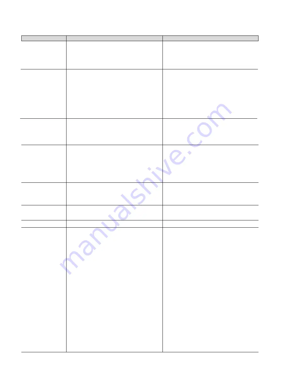
Troubleshooting Chart
These items should be checked by a qualified service techician only.
TROUBLE
CAUSE
CURE
1.
Blowers won’t operate
on COOL.
2.
Blowers operate on
COOL but compressor
doesn’t start.
3.
Blowers run on COOL
and compressor starts
but stops after a short
interval.
4.
Blowers run on COOL
and compressor starts
and runs, but compres-
sor occasionally stops
(on overload device).
5.
Compressor starts and
runs on COOL but
blowers do not run.
6.
Compressor starts and
runs on COOL but
blowers do not run.
7.
Equipment gives
electrical shock.
8.
Insufficient cooling
capacity.
a.
No power.
b.
Faulty pushbutton switch.
c.
Loose connections at pushbutton switch.
a.
Thermostat set too high.
b.
Heat valve is open and heat is on.
c.
Low voltage.
d.
Fault pushbutton switch.
e.
Faulty connection at pushbutton switch.
f.
Defective wiring to thermostat.
g.
Loose connections at compressor terminals.
h.
Wiring to compressor terminals defective.
i.
Loose connections in compressor overload device.
j.
Starting capacitor malfunctions (open circuited, short
circuited or loss of capacity.
k.
Defective compressor motor (short circuited, open
circuited, grounded).
a.
Operation of overload device due to overloading
compressor motor.
a.
Low voltage due to overloaded circuits within building or
throughout the local power system. Due to varying power
demands, this condition might exist only at certain times
during the day or on very hot days.
b.
High voltage due to fluctuations in local power system;
usually occurs at low load periods of the day.
c.
Partial short circuit in compressor motor. Under normal
loading a compressor with a partial short circuit might
appear to be operating all right; increased condensing air
temperature might then cause a short.
a.
Faulty pushbutton switch.
b.
Open circuited blower motor.
c.
Blower rubbing against its housing.
d.
Bearings on blower motor seized.
e.
Loose connection at pushbutton switch.
a.
Operation of the internally connected overload device
due to a short circuit in blower motor.
b.
Windings, rubbing of blower wheel or lack of lubrication
in blower motor bearings.
a.
Grounded electrical circuit.
a.
Equipment standing too long without being run.
b.
Insufficient airflow through condenser due to:
1)
Dirty condenser.
2)
Obstructed louvers on outer cabinet or wall box.
3)
Condenser blower/fan not running.
4)
Condenser blower/fan not up to speed.
5)
Condenser blower/fan slipping on motor shaft.
6)
Recirculation of condenser air.
c.
Insufficient airflow through evaporator due to:
1)
Dirty evaporator.
2)
Ice on evaporator coils.
3)
Dirty air filter.
4)
Obstructed discharge grilles.
5)
Evaporator blower motor not running.
6)
Evaporator blower motor not up to speed.
7)
Evaporator blower slipping on motor shaft.
d.
Heat load in room exceeds capacity of equipment.
e.
Windows and doors in room are open.
Continued on next page


