background image

29

Audyssey Setup

8. Do not adjust Volume during the measurements as this 

will cancel the measurements.

9. Do not hold the setup microphone in your hand during 

measurements.

10. Avoid placing the setup microphone close to a seat back 

or wall as sound reflections may give inaccurate results.

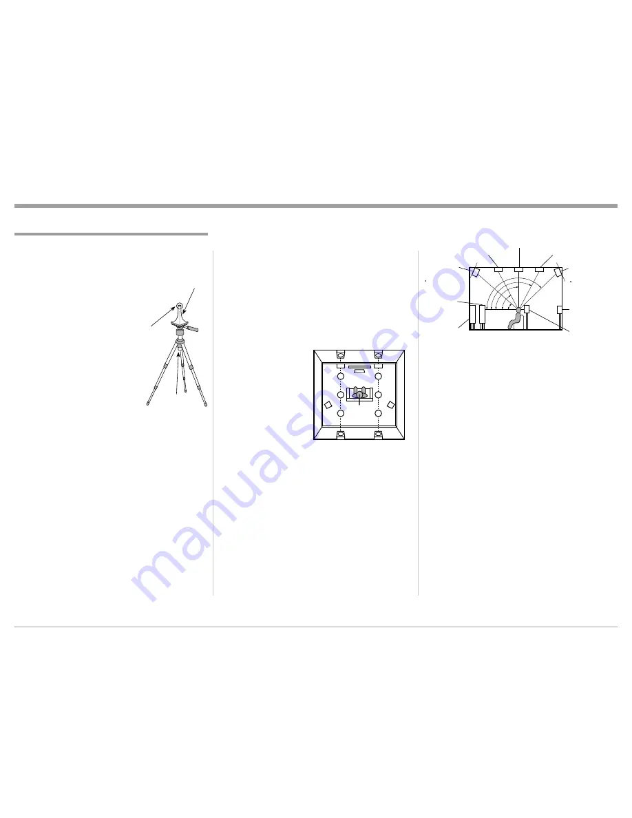
Measurements will be performed by placing the setup 

microphone successively at multiple positions through

-

out the entire listening area. For best results, we recom

-

mend you measure in 

six or more positions, as 

shown in the illustration 

(up to eight positions) 

about the main listening 

position (*M). Refer to 

figure 18A.

The main listening 

position is the position 

where listeners would 

normally sit or where 

one would normally 

sit alone within the 

listening environment. 

The ideal Loudspeaker 

Placement in a room for the best sonic effect is in the 

Side View Illustration. Refer to figure 18B. Both the 

Front Height and Rear Height Loudspeakers should 

be pointed slightly downward. Before starting Audys

-

sey Setup, place the setup microphone in the main 

listening position. Audyssey MultEQ

®

 XT32 uses the 

measurements from this position to calculate speaker 

distance, level, polarity, and the optimum crossover 

value.

The acoustic characteristics of the connected speak

-

ers and listening room are measured and the optimum 

settings are made automatically.

Assemble the supplied setup microphone and stand, 

then place it in the main listen-

ing position. Refer to figure 17.

Keep the following things in 

mind during the Audyssey pro

-

cedure:

1. When placing the setup micro

-

phone, adjust the height of the 

sound receptor to the level of 

the listener’s ear.

2. When performing Audyssey  

Setup, MultEQ

®

 XT32 Audys

-

sey Dynamic EQ

®

/ Audyssey 

Dynamic Volume

®

 functions 

become active. 

3. Make the room as quiet as 

possible. Background noise 

can disrupt the room measurements. Close windows, 

silence cell phones, televisions, radios, air condition

-

ers, fluorescent lights, home appliances, light dimmers, 

or other devices as measurements may be affected by 

these sounds.

4. Cell phones should be placed away from all audio 

electronics during the measurement process as Radio 

Frequency Interference (RFI) may cause measurement 

disruptions (even if the cell phone is not in use).

5. Do not unplug the setup microphone from the main unit 

until Audyssey Setup is completed.

6. Do not stand between the speakers and setup micro

-

phone or allow obstacles in the path while the mea

-

surements are being made. This will cause inaccurate 

readings.

7. Loud test sounds may be played during Audyssey  

setup. This is part of normal operation. If there is 

background noise in the room, these test signals will 

increase in volume.

When using a Powered Subwoofer(s) adjust the 

controls on the Subwoofer for neutral settings, as 

Audyssey will be making the adjustments of volume, 

crossover frequency, etc. Refer to the Subwoofer Own

-

ers Manual for additional information.

Proceed to "Audyssey Setup Procedure" on the 

next page.

Audyssey

®

 Auto Setup Information

Sound 

receptor

Setup Microphone

Microphone 

Stand

Figure 17

SL

TRL

RHL

RHR

FHL

TML

TFL

FL

SR

TRR

FHR

TMR

TFR

FR

C

(Viewed from the top)

Height speakers layout

*M

Figure 18A

1

2

3

4

5

Point slightly 

downwards

Front height 

speaker

1 30° - 45°

4 125° - 150°

2 30° - 55°

3 65° - 100°

5 135° - 150°

(Viewed from the side)

Top middle speaker

Top front speaker

Top rear speaker

Front speaker

Surround 

speaker

Surround 

back 

speaker

Front wide 

speaker

Point slightly 

downwards

Rear height 

speaker

Figure 18B

Содержание MX122

Страница 1: ...McIntosh Laboratory Inc 2 Chambers Street Binghamton New York 13903 2699 Phone 607 723 3512 www mcintoshlabs com MX122 A V Processor Owner s Manual ...

Страница 2: ...re le fonctionnement du dispositif Cet appareil numérique de la classe B est conforme à la norme NMB 003 du Canada 2 ATTENTION Afin de réduire le risque d interférence aux autres utilisateurs il faut choisir le type d antenne et son gain de façon à ce que la puissance isotrope rayonnée équivalente p i r e ne soit pas supérieure au niveau req uis pour l obtention d une communication satisfaisante C...

Страница 3: ...hat the device has passed the interoperability test conducted by the Wi Fi Alliance a group that certifies interoperability among wireless LAN devices Manufactured under license from Dolby Laboratories Dolby Dolby Atmos Dolby Surround and the dou ble D symbol are trademarks of Dolby Laboratories For DTS patents see http patents dts com Manufactured under license from DTS Inc DTS the Symbol DTS in ...

Страница 4: ...rovided for you to record that information Serial Number ________________________________ Purchase Date ________________________________ Dealer Name _________________________________ Table of Contents Safety Instructions 2 Separate Sheet Important Additional Operation Information Guide Trademark and License Information 3 Thank You and Please Take a Moment 4 Technical Assistance and Customer Servic...

Страница 5: ...cIntosh Technical Support 9 The IR Input with 1 8 inch mini phone jack is compatible with IR sensors such as a Xantech Model DL85K Kit Use a Connection Block such as a Xantech Model ZC21 when two or more IR sensors need to be connected to the MX122 To avoid possible interaction disable the MX122 Front Panel Sensor Refer to page 27 10 The DATA OUT Jack can be connected via a Y Adapter to more than ...

Страница 6: ...ield Ground PIN 2 Signal PIN 3 Signal TRIGger Power Control Connectors The MX122 Trigger Output Jacks send an On Off signal from 0 to 12 volts with a total current up to 50mA when connected to other Components A 3 5mm stereo mini phone plug is used for connection to the Trigger Outputs on the MX122 Data Output The MX122 Data Out sends Remote Control Signals to Source Components A 3 5mm mini phone ...

Страница 7: ... Channel Status Indicators The MX122 includes twenty five LEDs on the front panel to indicate what type of operating signals are being received signal processing mode and the output format chosen Audyssey DSX Audyssey DSX is a scalable system that adds new speakers to improve surround impression Audyssey DSX first adds Wide channels for the biggest impact on envelopment and then creates Height cha...

Страница 8: ...on for your MX122 Dimensions Front View of the MX122 Rear View of the MX122 17 1 2 44 5cm 7 5 8 19 4cm 7 1 8 18 1cm 6 3 8 16 2cm 13 1 4 33 7cm 17 1 8 43 5cm Side View of the MX122 16 1 2 41 9cm 3 16 0 5cm 13 16 2 1cm 6 9 16 16 7cm 10 9 16 26 8cm 14 1 2 36 8cm 2 5 1cm 1 15 16 4 9cm ...

Страница 9: ...low at least 2 inches 5 08cm above the top and 2 inches 5 08cm on each side so airflow is not obstructed Allow 19 1 2 inches 49 53cm depth behind the front panel Allow 1 7 16 inch 3 66cm in front of the mounting panel for knob clearance A custom cabinet installation should provide the minimum spacing dimensions for cool operation Al low at least 2 inches 5 08cm above the top 2 inches 5 08cm below ...

Страница 10: ...ions The identification of Rear Panel Connections for the MX122 A V Processor is located on a separate folded sheet contained in the Owner s Manual Packet Refer to separate sheet Mc1A for the Rear Panel Connections MX122 A V Processor Rear Panel ...

Страница 11: ... Cable from the MX122 DATA OUT Jack to one end of a Stereo 3 5mm Y adapter 9 Connect a Control Cable from the AM FM Tuner DATA IN Jack to another end of the Stereo 3 5mm Y adapter 10 Connect a Control Cable from the Audio Video Disc Player DATA IN Jack to the remaining end of the Stereo 3 5mm Y adapter IR In Connections 11 Optionally connect the Control Cable from the External IR Sensor to the MX1...

Страница 12: ...R Surround Right Channel to the Main Zone Power Amplifier matching channels respectively 6 Optional connect Balanced Audio Cables from the MX122 LRS Left Rear Surround Channel and RRS Right Rear Surround Channel to the Main Zone Power Amplifier matching channels respectively 7 Connect a Balanced Audio Cable from the MX122 SW1 Low Frequency Effects Channel also referred to as a Subwoofer Out to the...

Страница 13: ... using the default settings Power Control Connections 1 Connect a Control Cable from the MX122 TRIG ger Power Control 2 Jack to the Power Control In on Zone 2 Power Amplifier Note To assign the TRIGger 2 Output to activate when Zone 2 is selected requires changes to the default setting in the Setup Mode Refer to page 25 2 Connect any additional McIntosh Components in a similar manner as outlined i...

Страница 14: ...Display Controls and Push buttons The identification of the MX122 A V Processor Front Panel Display Controls and Push buttons is located on a separate folded sheet contained in the Owner s Manual Packet Refer to separate sheet Mc1B MX122 A V Processor Front Panel ...

Страница 15: ...e Control Push Buttons The identification of Remote Control Push Buttons for the MX122 A V Processor is located on a separate folded sheet contained in the Owner s Manual Packet Refer to separate sheet Mc4A for Push button iden tification ...

Страница 16: ...Screen Display on a Monitor TV connected to the HDMI Monitor 1 or 2 Output allows more information to be visible at the same time making it easier to navigate through the choices 2 Navigating thru and making changes to the Setup Menus are performed by using the HR088 Remote Control directional Up or Down Left or Right ENTER and the SETUP Push buttons The MX122 Front Panel Naviga tion Up Down Left ...

Страница 17: ...ntrol The MX122 will now connect to the Internet and check to see if a Firmware Update is available Refer to figures 10 and 11 6 Referring to figure 12 if it is desirable to switch Off the Automatic Firmware Notification use Directional Up or Down Push button on the Remote Control to select Notification followed by pressing the ENTER Push button 7 To switch Off the Firmware Update first press the ...

Страница 18: ...tments are grayed out except for Audyssey DSX until the Audyssey Room Correction has been applied refer to page 30 MultEQ XT32 Reference L R Bypass Flat Off Requires Audyssey Room Correction applied and Refer to the bottom of Video Screen for Information Dynamic EQ On Off Requires Audyssey Room Correction applied and Refer to the bottom of Video Screen for Information Dynamic EQ Reference Level Of...

Страница 19: ...to 12 For 1080P resolution Refer to the bottom of Video Screen for Information HDMI Setup Auto Lip Sync On Off Refer to the bottom of Video Screen for Information HDMI Audio Out AVP Off Requires HDMI Control Off Refer to the bottom of Video Screen for Information Video Output Auto Dual Monitor 1 Monitor 2 Refer to the bottom of Video Screen for Information Vertical Stretch Off On Refer to the bott...

Страница 20: ...ENU ITEM SUB MENU SELECTION OPTION S DESCRIPTION Inputs Input Assign Refer to Separate Sheet Mc MX122 Menu 4 and the Top Left Video Screen for the Default Input Assignment Information All of the default Input Names have already been assigned to the various signal type connectors on the rear panel of the MX122 They include HDMI Digital Video and Audio Digital Audio Coaxial and Optical Analog Audio ...

Страница 21: ...31 while performing the Audyssey Setup Amp Assign Is used to tell the MX122 and Audyssey how many loudspeakers there are their location in the room and their function Refer to the bottom of Video Screen for Information Channel Select For demo purposes allows for Audyssey to skip some of the loudspeakers to reduce the required measurement time and adjustment Refer to the bottom of Video Screen for ...

Страница 22: ...r two pairs of Front Loudspeakers Refer to the bottom of Video Screen for Information 2ch Playback Auto Manual When the Speaker Adjustments were performed in the Manual Mode the MX122 allows the 2ch Playback changes to become active when the audio mode is set to STEREO during playback Refer to the bottom of Video Screen for Information NETWORK SETUP MENU MENU ITEM SUB MENU SELECTION OPTION S DESCR...

Страница 23: ...Screen for Information Friendly Name McIntosh MX122 Home Theater Living Room Family Room Guest Room Kitchen Dining Room Master Bedroom Bedroom Den Of fice Other Refer to the bottom of Video Screen for Information Diagnostics Refer to Video Screen for status of the Physical Connection Router Access and Internet Access GENERAL SETUP MENU MENU ITEM SUB MENU SELECTION OPTION S DESCRIPTION Language Eng...

Страница 24: ...eo Screen for Information Zone Rename MAIN ZONE MAIN ZONE Refer to Separate Sheet Mc MX122 Menu 9 and the General Zone Rename Video Screen Refer to the bottom of Video Screen for Information ZONE2 ZONE2 ZONE3 ZONE3 Quick Select Names Quick Select 1 CBL SAT Uses the four QUICK SELECT Push buttons on the Remote Control to display on the screen a custom name that was entered Refer to Separate Sheet M...

Страница 25: ...reen for Information CBL SAT On Refer to the bottom of Video Screen for Information DVD On Refer to the bottom of Video Screen for Information Blu ray On Refer to the bottom of Video Screen for Information Game On Refer to the bottom of Video Screen for Information Media Player On Refer to the bottom of Video Screen for Information TV Audio On Refer to the bottom of Video Screen for Information AU...

Страница 26: ...ideo Screen for Information ZONE MAIN ZONE Select Source Name Sound Mode Input Mode and Decode Mode Type and Number of Connections HDMI Digital Analog Component Video and Composite Video Video Mode Content Type Video Conversation i p Scaler Refer to the bottom of Video Screen for Information ZONE2 Power Select Source and Volume Level Refer to the bottom of Video Screen for Information ZONE3 Power ...

Страница 27: ...nterference can occur between the signals To prevent possible operational problems it maybe necessary to disable the MX122 Front Panel Sensor Perform the following steps to disable the sensor 1 With the MX122 in STANDBY MODE press and hold down the Front Panel ENTER and RETURN Push buttons while pressing the STANDBY ON Push button When the MX122 Front Panel Nomenclature is illuminained release the...

Страница 28: ...ttings for your specific Loud speaker complement and location in the Home Theater Room This will not only assure the best acoustic performance using Audyssey Room Equalization Cor rection but it will also assure the best sonic perfor mance using the latest in surround sound technology built into the MX122 Please refer to the MX122 Menu separate folded sheets MX122 Menu 5 while per forming the foll...

Страница 29: ...ear 2 When performing Audyssey Setup MultEQ XT32 Audys sey Dynamic EQ Audyssey Dynamic Volume functions become active 3 Make the room as quiet as possible Background noise can disrupt the room measurements Close windows silence cell phones televisions radios air condition ers fluorescent lights home appliances light dimmers or other devices as measurements may be affected by these sounds 4 Cell ph...

Страница 30: ...ated by the small Balloons in the room illustration placed around the sitting area and the Main sitting position is indicated by number 1 8 Following the On Screen instructions place the microphone in the 2nd listening position and then press the ENTER Push Button on the Remote Control to select highlight on screen button Con tinue Refer to figure 22 9 Continue following the On Screen instructions...

Страница 31: ...cials shown during television programs 12 When the analysis and storage ends unplug the Sound Calibration Microphone from the SETUP MIC Jack on the Rear Panel and press Next Refer to figure 25 13 Select Details and press Enter to verify the measurement results Subwoofers may measure a greater reported dis tance than the actual distance due to added electri cal delay common in subwoofers Note Do no...

Страница 32: ...el Check the speaker connections Ambient noise is too high or level is too low There is too much noise in the room Speaker or subwoofer sound is too low Either turn off any device generating noise or move it away Perform again when the surroundings are quieter Check the speaker installation and the direction in which the speakers are facing Adjust the subwoofer s volume Front R None The displayed ...

Страница 33: ...33 ...

Страница 34: ...t going to be used for an extended period of time please remove the AC Power Cord from the AC Outlet Input Selection The INPUT Control selects the desired source and is indicated on the top line of the Front Panel Informa tion Display Refer to figure 20 The selection of the sources may also be accomplished by pressing the appropriate push button on the Remote Control Refer to figure 23 Using the M...

Страница 35: ...el Surround Encoded the front panel INPUT FORMAT LEDs FL FR and S will illuminate Note The S indicator will only illuminate on some surround encoded program material C If the Analog Input Signal Source is Stereo the INPUT FORMAT LEDs FL and FR will illuminate D If an Analog Input Signal Source is Mono both channels will be receiving the mono signal and the INPUT FORMAT LEDs FL and FR will illumina...

Страница 36: ...exit Setup Mode Refer to the set of MX122 Menu separate folded sheets MX122 Menu 1 thru Menu 9 These separate sheets are con tained in the Owner s Manual Packet Return When the MX122 is in Setup Mode it is used for re turning to a previous Menu Screen Enter When the MX122 is in the Setup Mode press the EN TER Push button on the Front Panel or on the Remote Control to select the highlighted option ...

Страница 37: ...reo CD disc The settings include AUTO default setting the MX122 chooses the best signal processing DIRECT bypasses Back Surround and Front Height Channel processing and PURE DIRECT bypasses all digital processing Note When switching between the three modes the sound is momentarily muted 5 The menu item selected in step 4 was Playlists now select from the various Playlists Menu Items Refer to figur...

Страница 38: ...22 Menu 8 3 Launch iTunes and click the AirPlay icon displayed in the upper left of the window and then select the MX122 from the list to allow the streaming music from the computer iTunes program to the MX122 Refer to figures 33 and 34 AirPlay Figure 33 AirPlay icon 4 Choose a song and click Play in iTunes The music will stream to the MX122 Refer to figure 35 Streaming music from iPhone iPod touc...

Страница 39: ... computer via the USB port of this unit using a USB cable Compatible Formats USB Memory Devices A thru C WMA Windows Media Audio Yes D MP3 MPEG 1 Audio Layer 3 Yes WAV Yes MPEG 4 AAC Yes E FLAC Free Lossless Audio Codec Yes JPEG Yes ALAC1 DSD AIFF A This unit is compatible with MP3 ID3 Tag Ver 2 standard B This unit can show the artwork that was embedded by using MP3 ID3 Tag Ver 2 3 or 2 4 C This ...

Страница 40: ...Refer to figure 46 Note The Station selected WSKG 89 3 FM is lo cated in the Binghamton NY area 3 Press the ENTER Push button on the Remote Control and the MX122 will now access WSKG 89 3 FM Refer to figure 47 4 There are Internet Radio Stations that are ac cessable by selecting Search Stations and then Location Refer to figures 45 and 48 Follow the on screen menus to access the station s you desi...

Страница 41: ...s required to Register Login In Sign In for some Internet Media Streamers including McIntosh s own special site In return for registering the Internet Media Streamers usually provide easier use access to other information or additional functions Before registering at the McIntosh vTuner Site please look up the MAC Address unique Identifi cation Number ID for each MX122 as it will be entered in the...

Страница 42: ...ng up AirPlay 3 Download the Spotify Music App from the Apple App Store using your Apple Mobile Device with direct Internet access or via the iTunes Com puter Program with your Apple Mobile Device directly connected to the computer 4 Using the Apple Mobile device select the Spotify App Icon refer to figure 58 Referring to figure 59 select the Spotify Icon 5 Select Account from the Spotify Menu to ...

Страница 43: ...digital music files and or dig ital picture files The PC Computer and the NAS unit need to be connected to the same Router Network as the MX122 The NAS unit also needs to be compatible with the consumer electronics DLNA Digital Living Network Alliance Standard Follow the steps below to access the music and or pictures via the MX122 1 Press the ONLINE MUSIC Push button and then select Media Server ...

Страница 44: ...d operating the MX122 An important function the computer permits is the creation of a PC File containing all the current MX122 Setup Settings Data to be saved Refer to figure 80 When necessary all of the MX122 Setup Settings previously saved to the PC File can be restored by reloading the data back into the MX122 Figure 78 Figure 79 Figure 80 Figure 81 Refer to figure 81 For additional informa tio...

Страница 45: ...on t Resetting the Microprocessors The following steps will return the MX122 to factory default settings 1 Press the STANDYBY On Push button to switch Power OFF to the MX122 Refer to figure 82 2 When the unit is OFF press and hold in the MOVIE and MUSIC Front Panel Push buttons followed by pressing the STANDBY ON Push button 3 When the MX122 is powered ON and all the Front Panel Information Displa...

Страница 46: ...0 Volts 50 60Hz at 75 watts 120 Volts 50 60Hz at 75 watts 220 Volts 50 60Hz at 75 watts 230 Volts 50 60Hz at 75 watts 240 Volts 50 60Hz at 75 watts Standby less than 0 5 watt Note Refer to the rear panel of the MX122 for the correct voltage Overall Dimensions Width is 17 1 2 inches 44 45cm Height is 7 5 8 inches 19 37cm including feet Depth is 19 1 2 inches 49 53cm including the Front Panel Knobs ...

Страница 47: ...ratory Refer to page 4 Please see the Part List for the correct part numbers Quantity Part Number Description 1 034256 Shipping carton only 4 033887 End cap 2 034493 Spacer pad 1 033697 Inside carton only 1 033725 Inner carton top pad 1 034574 Bottom pad 2 034446 Foam plug 4 017937 Plastic foot 4 400159 10 32 x 3 4 screw 4 404080 10 Flat washer 1 034499 Accessory Box 1 034500 Slotted foam 1 034501...

Страница 48: ...ucts is the policy of McIntosh Laboratory Incorporated who reserve the right to improve design without notice Printed in the U S A McIntosh Laboratory Inc 2 Chambers Street Binghamton NY 13903 www mcintoshlabs com McIntosh Part No 04176200 ...

Отзывы: