160GR Natural Gas Booster Instruction Manual
Mayekawa all rights reserved. Subject to change without notice. Lat revised in October 2007
p.27
7.4.4 Balance Piston Cover
7.4.4.1 Disassembly
a
)
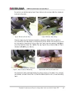
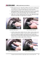
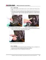
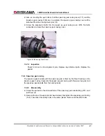
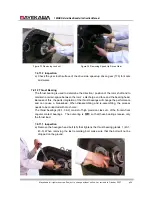
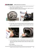
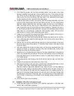
Remove the top 2 hexagon socket head screws (24), and insert safety bolts. Remove
all the other hexagon socket head screws (24).
Figure 16 Removing Bolts on Balance Piston Cover
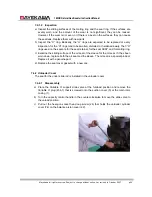
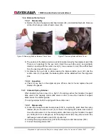
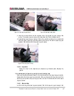
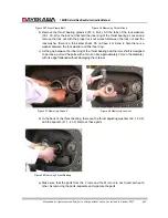
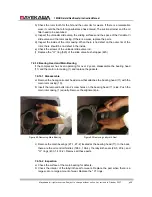
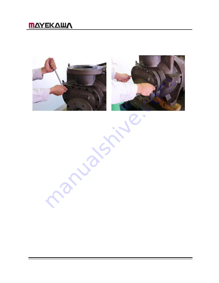
Figure 17 Removing Balance Piston Cover
b
)
The position of the balance piston cover (22) is determined by the alignment pin (596).
There are 2 openings for the eye bolts. Insert the eye bolts evenly, and gradually
create an opening with the suction cover (5). Use a receiver to catch the oil that flows
from the opening with the suction cover.
c
)
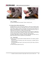
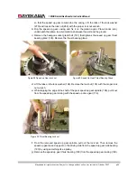
As drawing the eye bolts in while keeping the balance piston cover (22) and the
suction cover (5) in parallel, the balance piston will be detached from the alignment
pins.
7.4.4.2 Inspection
a
)
Check for any bent on the alignment pins. When a bent is found, replace the part.
Replace the gasket.
7.4.5
Unloader Spring Retainer
When transferring from a low Vi to a high Vi, the spring pushes the Variable Vi support
slide valve to the capacity control slide valve in order to move the Variable Vi support
slide valve to the discharge side.
The spring retainer holds the spring with the suction cover.
7.4.5.1 Disassembly
a
)
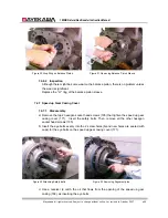
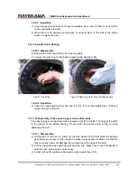
Loosen the hexagon socket head screws (452) in a symmetry, which fixes the spring
retainer (84) on the suction cover (5). As there is the spring (83) inside, make sure to
move the slide valve is at the unload position after removing the Variable Vi support
pin. Failing to do so is dangerous, as the spring retainer (84) may jump out when the
last hexagon socket head screw (452) is pulled out.
b
)
Holding the spring retainer (84), pull out the hexagon socket head screw (452).
c
)
Pull out the spring retainer (84).

