160GR Natural Gas Booster Instruction Manual
Mayekawa all rights reserved. Subject to change without notice. Lat revised in October 2007
p.35
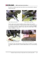
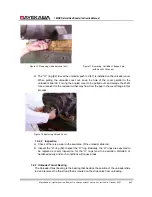
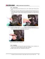
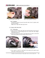
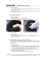
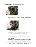
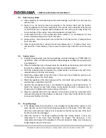
Figure 35 Thrust Cramp Bolt
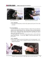
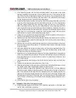
Figure 36 Removing Thrust Gland
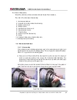
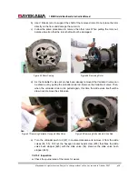
b) Remove the thrust bearing glands 2 (43-2, 43-4). Lift the tabs of the lock washers
(39-1, 39-2) for the lock nut that hold the inner-ring of the thrust bearings. Loosen and
remove the lock nut with the proper lock nut wrench. Between the lock nut and the
lock washer, there is a think steel sheet. Do not lose it or bend it. Also there is a
washer between the lock washer and the inner-ring.
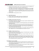
c) As the gap between the inner-ring of the thrust bearing and the rotor shaft is designed
to be loose, pull out the parts with a thin iron bar, approximately 3mm in the diameter,
with its edge flattened without damaging the retainer.
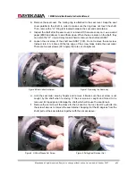
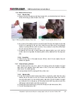
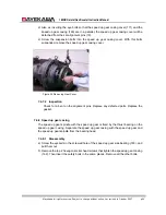
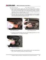
Figure 37 Removing Gland 2
Figure 38 Removing Lock nut
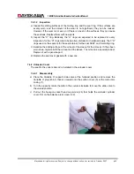
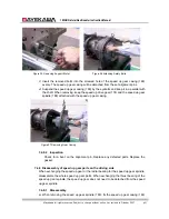
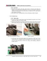
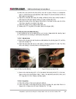
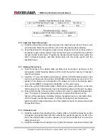
d) In the back of the thrust bearing, there are the thrust adjusting washers (42-1, 42-2)
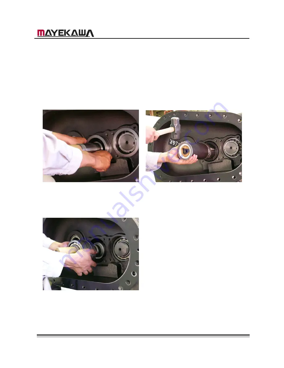
and the spacers (41-1, 41-2). Remove these parts.
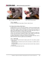
Figure 39 Removing Thrust Bearing
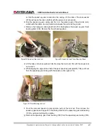
e) Make sure that the parts from the F rotor and the M rotor are not mixed with each
other. As removing the parts, separate and organize the parts.

