160GR Natural Gas Booster Instruction Manual
Mayekawa all rights reserved. Subject to change without notice. Lat revised in October 2007
p.39
b) Check the rotor tooth for the hit and the outer rim for wears. If there is a remarkable
wear, it could be that a foreign substance has entered. The suction strainer and the oil
filter need to be examined.
c) Inspect the unloader slide valve, the sliding surfaces and the space of the Variable Vi
slide valve and the rotor casing. If there is a wear, replace the parts.
d) Inspect the inside of the rotor casing. When there is no defect on the outer rim of the
rotor, there should be no defect in the inside.
e) Check the screws of the unloader slide valve rod.
f) Replace the
“
O
”
ring (523) of the slide valve bush stopper (445).
7.4.14 Bearing Head and Main Bearing
If the compressor has been operating for over 2 years, disassemble the bearing head
(11) and the main rotor casing (1) and replace the gaskets.
7.4.14.1 Disassemble
a
)
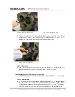
Remove the hexagon socket head screw that attaches the bearing head (11) with the
main rotor casing (10).
b
)
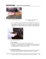
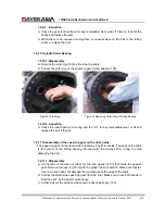
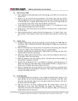
Insert the removed bolts into 2 screw holes on the bearing head (11) side. Push the
main rotor casing (1) equally. Remove the alignment pin.
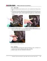
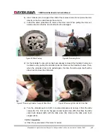
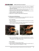
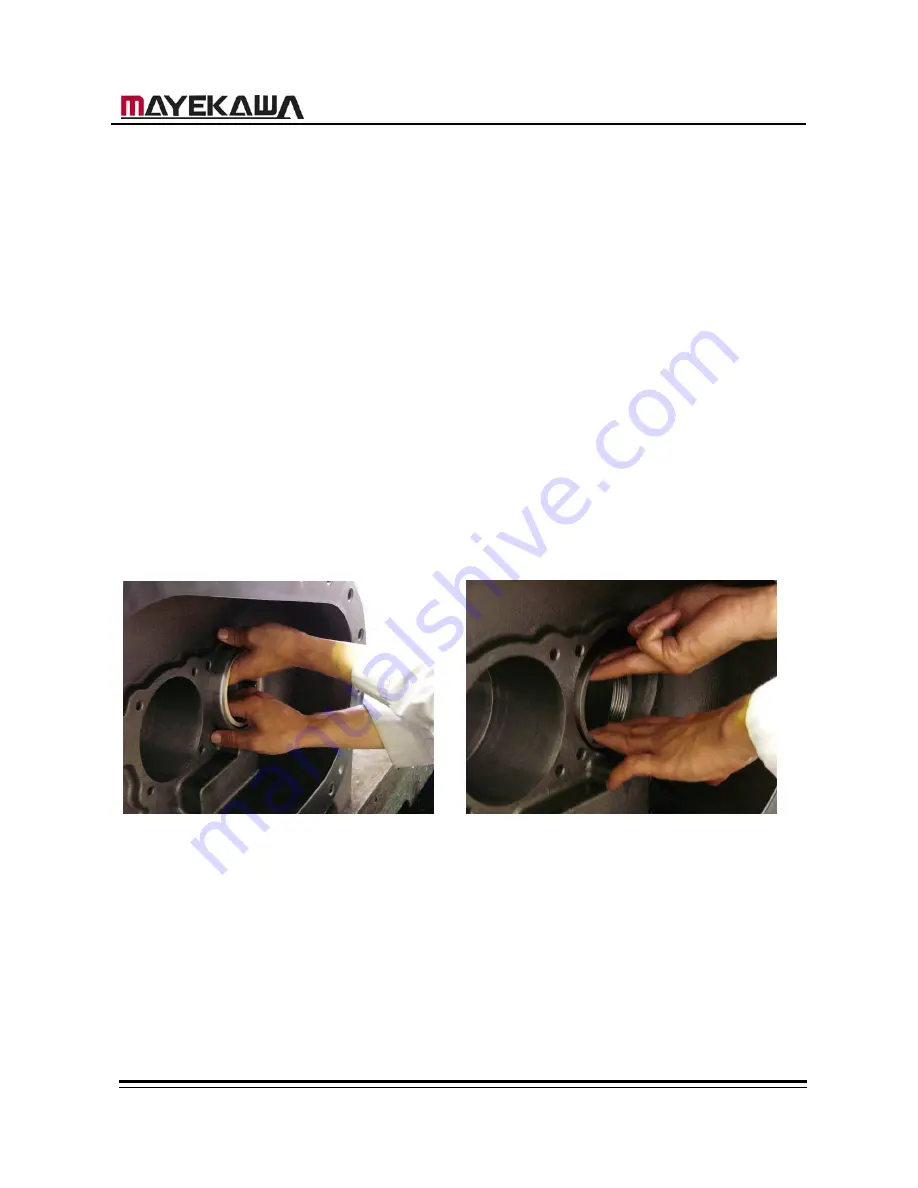
Figure 49 Removing Main Bearing
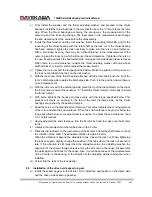
Figure 50 Removing Labyrinth Seal
c
)
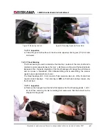
Remove the main bearings (27-1, 27-2) located at the bearing head (11). In the back,
there are the oil control throttles (196-3, 196-4), the labyrinth seals (29-3, 29-4), and
“
O
”
rings (433-1, 433-2). Remove all these parts.
7.4.14.2 Inspection
a
)
Check the surface of the main bearing for defects.
b
)
Check the interior of the labyrinth seal for wears. Replace the part when there is a
large scar or a large amount of wear. Replace the
“
O
”
rings.

