160GR Natural Gas Booster Instruction Manual
Mayekawa all rights reserved. Subject to change without notice. Lat revised in October 2007
p.43
b
)
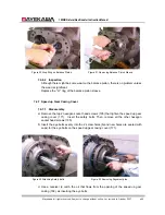
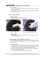
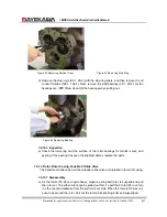
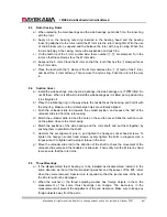
Install the driven side speed up gear, the driven side gear spacer, the lock washer, and
the packing in this order. Then use a wrench to tighten the lock nut.
c
)
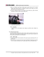
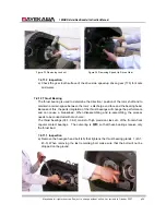
Then, make sure the vibration on the journal area of the shaft edge with a dial indicator
by turning the rotor by hand. The allowable range of the vibration is within 0.33mm.
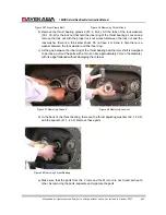
When the measurement is beyond the allowable range, loosen the lock nut. Then slowly
tighten the lock nut, changing the position of the groove the lock nut where the lock nut
wrench is laid.
d
)
Fold the tables of the lock washer in the end.
8.6
Spindle Roller Bearings
a
)
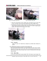
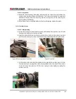
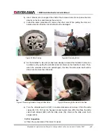
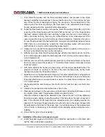
Insert the outer-ring of the spindle roller bearing in the bearing head.
b
)
Install the stop ring by the stop ring pliers, and fix the roller bearing.
8.7
Building the Driving Side speed up Gear
a
)
If the radial bearing has been replaced with a new part, conduct a thermal insert on the
inner-ring and the speed up gear spindle.
b
)
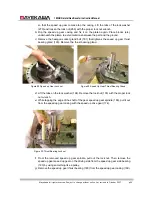
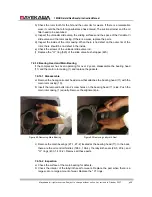
Install the thrust bearing for spindle in the speed up gear casing. Fix the thrust bearing
fixing jig by hex bolts.
c
)
Place and fix the speed up gear casing in the way that the thrust bearing side comes to
the bottom. Insert the speed up gear spindle into the inner-ring of the thrust bearing.
d
)
Install the driving side speed up gear spacer and the driving side speed up gear key.
Then install the driving side speed up gear.
e
)
Insert the driving side speed up gear spacer, the lock washer, and the packing in this
order. Tighten the lock nut with the specified torque by the lock nut wrench.
8.8
Installation of speed up Gear Casing
a
)
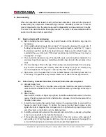
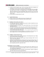
Install the speed up gear casing with the driving gear in the bearing head. Screw 2 safety
bolts in the tap holes on the bearing head.
b
)
With the eye bolt, suspend the speed up gear casing horizontally. Install it into the
bearing head, locking the gears.
c
)
Hammer in the set alignment pins, and tighten them by hexagon socket head screws. To
tighten the hexagon socket head screws, tighten the bolts in diagonal positions, and then
tighten them with the torque wrench with the specified torque. The bolts on the bottom
are to be tightened when the compressor is lifted.
8.9Installation of speed up Spindle
a
)
Remove the thrust bearing fixing jig from the speed up gear casing. Attach the lock nut
and the packing with the speed up gear spindle. Use the lock nut wrench to tighten the
lock nuts with the specified torque.
b
)
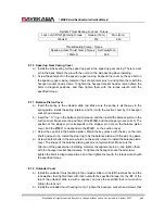
Having tightened the lock nuts, fold the tabs of the lock washer. Tighten the speed up
gear thrust cramps with the torque specified below.

