background image


160GR Natural Gas Booster Instruction Manual 


Mayekawa all rights reserved. Subject to change without notice. Lat revised in October 2007 

p.4 


1. Introduction 

The 160GR is a compressor engineered for the natural gas booster. Provided that it will be 
operated by an engine, the compressor itself has an internal speed up gear that allows 
different ratios according to the required air volume. 
Also, the Vi on the outlet port can be changed in 4 steps with the manual capacity control as 
the standard. 


2. Capacity Control Procedures 

On the standard 160GR specification, the capacity control is done manually by a handle. 
Turning the handle in clockwise is for loading, and turning it in counter-clockwise is for 
unloading. 
The slide valve for the capacity control is fully loading when it is in contact with the surface of 
the variable Vi slide valve. The position of Unload is determined by the stopper equipped on 
the surface of the under slide rod. 
Therefore, the position of full-load of the slide valve depends on the selected Vi; therefore, 
the strokes of the slide valve vary as well. The strokes of the slide valve for each Vi setting 
are described below. 


[CAUTIONS] 


Although there are stopper structures on the full-load position and the minimum load 
position, do not turn the handle with unnecessary force when attempting capacity control. 


When loading, turning the handle with a relatively little force can easily move the slide valve. 
When the slide valve is in contact with t 


the variable Vi slide valve for full-load, the handle becomes heavy. Then, forcing the handle 
to turn may lead to the internal damage.   


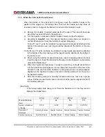
Garph2.1 Strokes for Slide Valve for Each Vi 

Vi Setting 

The number of rotation 

Unload 

 Full-Load 

2.3 29

1/2 

2.63 26 
3.65 21 

5.0 17-1/3 


3.  Variable Vi Structure 

To change the Vi on the outlet port, the size of the radial outlet port needs to be changed by 
moving the variable Vi supplementary slide valve on the full-load. 
The variable Vi supplementary slide valve is fixed to the case by fix pins through pin holes on 
the Variable Vi slide valve. The pin holes are located to accommodate the 4 different Vi 
settings so that the Vi can be changed step-by-step. 
On 160GR, the fix pins of the Variable Vi slide valve are attached from the outside of the case. 
When the pins are removed, the interior gas will be discharged to the air. When changing Vi 

Содержание 160 GR

Страница 1: ...wa all rights reserved Subject to change without notice Lat revised in October 2007 p 1 160 GR Natural Gas Booster Disassembly and Re Assembly Instruction Manual This manual is to provide instructions how to disassemble and re assemble the 160GR machine ...

Страница 2: ...7 4 3 Unloader Thrust Bearing 25 7 4 4 Balance Piston Cover 27 7 4 5 Unloader Spring Retainer 27 7 4 6 Balance Piston Balance Piston Sleeve 28 7 4 7 Speed up Gear Casing Cover 29 7 4 8 Speed up gear casing 30 7 4 9 Disassembly of speed up gear parts on the driving side 31 7 4 10 Spindle Roller Bearing 33 7 4 11 Disassembly of the speed up gear on the driven side 33 7 4 12 Thrust Bearing 34 7 4 12 ...

Страница 3: ...served Subject to change without notice Lat revised in October 2007 p 3 8 9 Installation of speed up Spindle 43 8 10 Speed up Gear Casing Cover 44 8 11 Balance Piston Cover 44 8 12 Unloader Cover 44 8 13 Mechanical Shaft Seal 45 9 Procedures to Adjust End Clearance 45 ...

Страница 4: ... well The strokes of the slide valve for each Vi setting are described below CAUTIONS Although there are stopper structures on the full load position and the minimum load position do not turn the handle with unnecessary force when attempting capacity control When loading turning the handle with a relatively little force can easily move the slide valve When the slide valve is in contact with t the ...

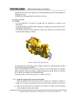
Страница 5: ...ding with changing Vi settings Figure1 Variable Vi Structure Cut up View The compressor is set at the M port when shipped Choose the most appropriate Vi setting for the expected operating conditions When the appropriate port is to be other than the M port the Vi setting needs to be changed before operations When the pressure conditions dramatically change during an operation the Vi needs to be cha...

Страница 6: ... of the rotor casing The plug should be attached to the bottom of the suction cover f After moving the variable Vi slide valve put the Vi guide pin into the case and lock them with the hexagon socket head cap screws With the Variable Vi support guide pin use the dice studs for the seal When the Vi guide pin feels heavy or caught by something it should not be forced into the holes When this happens...

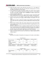
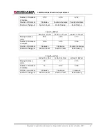
Страница 7: ...ng From the M Port M Port K Port M Port L Port M Port H Port Moving Distance mm 50 5 29 5 21 5 Number of Rotations of Handle 8 3 8 4 7 8 3 5 8 Direction of Rotations Clockwise Clockwise Counter Clockwise Position of fixing pin Suction Cover Suction Cover Rotor Casing From the H Port H Port K Port H Port L Port H Port M Port Moving Distance mm 72 51 21 5 Number of Rotations of Handle 12 8 1 2 3 5 8...

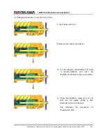
Страница 8: ... K Port to L Port the Position of K Port Remove the Variable Vi guide pin Turn the capacity control handle 3 1 2 times in counter clockwise and move the Variable Vi slide valve to the L port position Screw the Variable Vi guide pin in If it is tight turn the handle slightly in both directions and find a loose spot This completes the procedures for changing to L Port ...

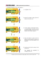
Страница 9: ...bottom of the suction cover Turn the capacity control handle 4 7 8 times in counter clockwise and remove the set bolt from the bottom of the rotor casing Replace it with Variable Vi guide pin Screw the Variable Vi guide pin into the bottom of the rotor casing If it is tight turn the capacity control handle slightly in both directions Lock the set bolt into the bottom of the suction cover This comp...

Страница 10: ...otor casing and the plug should be attached to the bottom of the suction cover d After moving the Variable Vi support slide valve insert Vi support guide pin and lock it with the hex bolt Insert the dice stud for the seal into the Variable Vi support slide valve before tightening it e When the Vi guide pin feels heavy or caught by something it should not be forced into the holes When this happens ...

Страница 11: ...160GR Natural Gas Booster Instruction Manual Mayekawa all rights reserved Subject to change without notice Lat revised in October 2007 p 11 ...

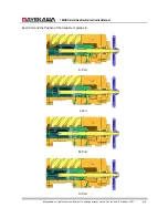
Страница 12: ...al Gas Booster Instruction Manual Mayekawa all rights reserved Subject to change without notice Lat revised in October 2007 p 12 Each Port and the Position of the Variable Vi guide pin K Port L Port M Port H Port ...

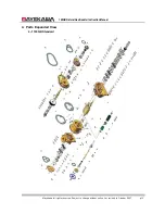
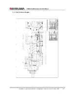
Страница 13: ...160GR Natural Gas Booster Instruction Manual Mayekawa all rights reserved Subject to change without notice Lat revised in October 2007 p 13 4 Parts Expanded View 4 1 160GR Standard ...

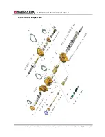
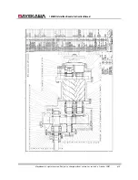
Страница 14: ...160GR Natural Gas Booster Instruction Manual Mayekawa all rights reserved Subject to change without notice Lat revised in October 2007 p 14 4 2 160GR with Integral Pump ...

Страница 15: ...4 3 Mayek Parts Stru 16 kawa all rights cture Diagr 0GR Natural G reserved Sub ram Gas Booster I bject to change nstruction Ma e without notice anual e Lat revised i in October 200 07 p 15 5 ...

Страница 16: ...Mayek 16 kawa all rights 0GR Natural G reserved Sub Gas Booster I bject to change nstruction Ma e without notice anual e Lat revised i in October 200 07 p 16 6 ...

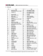
Страница 17: ...TOR 169 SPEED UP GEAR CASTING 27 1 MAIN BEARING M 170 GASKET SPEED UP GEAR CASTING 27 2 MAIN BEARING F 171 SPEED UP GEAR CASTING COVER 28 1 SIDE BEARING M 172 GASKET SPEED UP GEAR CASTING COVER 28 2 SIDE BEARING F 174 SPEED UP DRIVE GEAR 29 1 STOP RING 175 SPEED UP DRIVE GEAR KEY 29 2 STOP RING 176 SPEED UP GEAR SPACER 29 3 LABYRINTH SEAL M 179 SPEED UP DRIVEN GEAR 29 4 LABYRINTH SEAL F 180 SPEED ...

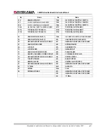
Страница 18: ...ASHER E 54 UNLOADER SLIDE VALVE 1 196 5 OIL CONTROL THROTTLE SPEED UP GEARS 55 UNLOADER SLIDE VALVE 2 246 UNLOADER SLIDE VAVLE GUIDE 58 HEXAGON SOCKET HEAD CAP SCREW 247 HEXAGON SOCKET HEAD CAP SCREW 67 UNLOADER PUSH ROD 248 SPRING WASHER 69 LOCK NUT 249 ALIGNMENT PIN 70 LOCK WASHER 273 HEXAGON NUT 74 UNLOADER CYLINDER COVER 280 PLAIN WASHER 75 GASKET UNLOADER CYLINDER COVER 289 VI VARIABLE SLIDE ...

Страница 19: ...160GR Natural Gas Booster Instruction Manual Mayekawa all rights reserved Subject to change without notice Lat revised in October 2007 p 19 6 Outer Dimension ...

Страница 20: ...an for drained oil and waste cloth etc Use a large platen for the process and choose a dry large environment with the least amount of dust or sand Removing the Compressor 7 1 Interior Gas Recovery When the screw compressor is at a stop the inside pressure of the compressor is very high Equalize the pressure with the lower pressure side Then recover the gas to equalize the pressure as the air press...

Страница 21: ...tract the oil in advance The oil inside can be extracted by removing the plug on the bottom of the suction cover and the rotor casing or plug 454 2 on the suction cover Also loosen the Variable Vi 弁位置決め pin at the same time note the 二面幅 of the hex head of the set bolt is 288mm That of Variable Vi 弁位置きめ pin is 30mm Figure 3 when set bolt is on Rotor casing Figure 4 when set bolt is on Suction Cover...

Страница 22: ...d main bearing 7 4 1 Mechanical Shaft Seal 7 4 1 1 Disassembly This compressor uses a Balance type single seal for the mechanical seal Carbon and special cast iron are used for the sliding surface The moving part is sealed with bellows and an O ring is used for the packing gland a Remove 4 out of the 6 bolts with the hex head 53 on the seal cover 51 leaving 2 bolts in a symmetry position Then loos...

Страница 23: ...he set screw of the shaft seal ASSY 100 Do not remove the set screw Instead turn it 3 4 times till the top edge of the screw hides inside the seal collar There are two set screws 90 angle that are out of alignment Figure 6 Seal Collar Set Screw Figure 7 Removing the Seal body e Hold the seal collar area by fingers and remove it Make sure the set screw is not caught by the shaft when removing If th...

Страница 24: ...eal are for the seal retainer for the seal ASSY and for mating ring c Examine the sliding surface of the oil seal of the sleeve for the oil seal If it has been worn down replace both the oil seal and the sleeve The oil seal is a special product Replace it with a genuine part d Replace the seal cover gasket with a new one 7 4 2 Unloader Cover The seal for the under slide rod is installed in the unl...

Страница 25: ... out can damage the shaft Use a receiver for the residual oil that may flow from the gap in the cover flange in this process Figure 12 Removing Unload Cover 7 4 2 2 Inspection a Check of there is a wear in the seal area of the unloader slide rod b Inspect the O ring 82 Inspect the O ring Basically the O rings are expected to be replaced at every inspection for the O rings tend to be swollen distor...

Страница 26: ...ench To loosen the lock nut 69 hold the area in the front edge of the unloader push rod 67 with the spanner Figure 13 Unloader Trust Bearing Cram bolt Figure 14 Unloader Thrust Bearing Lock nut c Remove the thrust washer 79 located between the unloader thrust bearing and the lock nut Then pull out the unloader TAC bearing 273 Figure 15 Removing Unloader Thrust Bearing 7 4 3 2 Inspection a Wash the...

Страница 27: ...rallel the balance piston will be detached from the alignment pins 7 4 4 2 Inspection a Check for any bent on the alignment pins When a bent is found replace the part Replace the gasket 7 4 5 Unloader Spring Retainer When transferring from a low Vi to a high Vi the spring pushes the Variable Vi support slide valve to the capacity control slide valve in order to move the Variable Vi support slide v...

Страница 28: ...e thrust load which results in a longer life span of the bearing This piston is the balance piston On the F rotor side however the gas load towards in the thrust direction is smaller than on the M rotor and the number of rotations is smaller as well Therefore the F rotor does not need a balance piston to assure a long life span of the thrust bearing The balance piston sleeve is structured to keep ...

Страница 29: ... piston sleeve 7 4 7 Speed up Gear Casing Cover 7 4 7 1 Disassembly a Remove the top 2 hexagon socket head screws 195 that tighten the speed up gear casing cover 171 Insert the safety bolts Then remove all the other hexagon socket head screws 195 b Insert the eye bolts evenly into the 2 screw holes brand new holes are sealed with caps for the eye bolts on the speed up gear casing cover 171 Figure ...

Страница 30: ...ing cover Figure 24 Removing Gear Cover 7 4 7 2 Inspection Check for a bent on the alignment pins Replace any defected parts Replace the gasket 7 4 8 Speed up gear casing The speed up gear spindle with the speed up gear is fixed by the thrust bearing on the speed up gear casing Separate the speed up gear casing with the speed up gear and the speed up gear spindle from the bearing head 7 4 8 1 Disa...

Страница 31: ...ng keep the speed up drive gear 174 and the speed up gear spindle 188 attached with the speed up gear casing Figure 27 Removing Gear Casing 7 4 8 2 Inspection Check for a bent on the alignment pin Replace any defected parts Replace the gasket 7 4 9 Disassembly of speed up gear parts on the driving side When exchanging the speed up gear or the radial bearing for the speed up gear spindle disassembl...

Страница 32: ...ed up gear thrust bearing gland 190 Remove the thrust bearing gland Figure 28 Speed up Gear Lock nut Figure 29 Speed Up Gear Thrust Bearing Gland d Lift the tabs on the lock washer 194 Remove the lock nut 193 with the proper lock nut wrench e While tapping the edge of the shaft of the gear speed up gear spindle 188 pull it out from the speed up gear casing with the speed up drive gear 174 Figure 3...

Страница 33: ... Inspection a Check the roller bearing inner ring and the コロ for any remarkable wear or hit and replace the part if there is 7 4 11 Disassembly of the speed up gear on the driven side The speed up gear on the driven side is located at the M rotor side The edge of the shaft is the journal of the sliding bearing Proceed with the process after curing to avoid damaging the part 7 4 11 1 Disassembly a ...

Страница 34: ...space between the rotor s discharge end face and the bearing head Because of this the parts integration of the thrust bearings will change the performance and can cause a breakdown When disassembling and re assembling the process needs to be conducted with much care The thrust bearings 38 1 38 2 consist of high precision class etc of the front to front angular contact bearings The outer ring is 隙間...

Страница 35: ...et Do not lose it or bend it Also there is a washer between the lock washer and the inner ring c As the gap between the inner ring of the thrust bearing and the rotor shaft is designed to be loose pull out the parts with a thin iron bar approximately 3mm in the diameter with its edge flattened without damaging the retainer Figure 37 Removing Gland 2 Figure 38 Removing Lock nut d In the back of the...

Страница 36: ...earings replace the parts 7 4 12 Suction Cover 7 4 12 1 Disassembly a Loosen the hexagon socket head cap screw 2 that attach the suction cover 5 with the main rotor casing 1 and remove them b Insert the removed screws into the screw holes for eye bolts on the suction cover and push the rotor casing 1 evenly Insert them slowly alternating left and right in turns Figure 40 Removing Suction Cover Bol...

Страница 37: ...nspection a Check the inner ring and the surface of the roller bearings for tarnish scars and peeling If the bearing has even the slightest defect replace the parts 7 4 13 Rotor Rotor Casing Variable Vi Slide Valve The Variable Vi slide valve and the unloader slide valve are installed in the rotor casing 7 4 13 1 Disassembly a As the rotors 25 26 are quite heavy prepare a sling belt etc to suspend...

Страница 38: ...ble Vi valve set pin has been already removed the Variable Vi valve can be drawn out by pulling the unloader slide rod Remove the Variable Vi valve Then when the unloader slide rod is pulled again this time the slide valve itself will be drawn out Remove the slide valve Figure 47 Removing Variable Vi support Slide Valve Figure 48 Removing Slide Valve Slide Rod e Turn the unloader push rod 67 in co...

Страница 39: ...sh stopper 445 7 4 14 Bearing Head and Main Bearing If the compressor has been operating for over 2 years disassemble the bearing head 11 and the main rotor casing 1 and replace the gaskets 7 4 14 1 Disassemble a Remove the hexagon socket head screw that attaches the bearing head 11 with the main rotor casing 10 b Insert the removed bolts into 2 screw holes on the bearing head 11 side Push the mai...

Страница 40: ... they should be inserted quite smoothly When the bearings do not go in smoothly they are not straight to the housing Use a pad and tap them to straighten them e Apply some oil to the gasket that is to be installed between the bearing head and the rotor casing The gasket is not symmetric Make sure to attach it in the right direction 8 2 Rotor Casing Unloader Slide Valve Variable Vi Slide Valve Bear...

Страница 41: ...ring and hold it with the stop ring Make sure the oil discharge holes are vertically aligned c Push the unloader slide rod towards the unload position and expose the half of the unloader slide rod from the rotor casing d Match the unloader slide rod and the hole on the suction cover Slide the suction cover on the platen close to the rotor casing e Match the positions of the side bearing and the ro...

Страница 42: ...the rotor moved to the discharge side place the tip of the dial indicator on the top of the rotor suction and set the needle at 0 Install the thrust cramp 2 Get ready to install the thrust cramp 1 h With bolts tightens the bearing cramps evenly with the torque specified below This process will create an opening in the top of the rotor discharge side as the thrust bearings are pushed by the bearing...

Страница 43: ...in the way that the thrust bearing side comes to the bottom Insert the speed up gear spindle into the inner ring of the thrust bearing d Install the driving side speed up gear spacer and the driving side speed up gear key Then install the driving side speed up gear e Insert the driving side speed up gear spacer the lock washer and the packing in this order Tighten the lock nut with the specified t...

Страница 44: ...ng in the balance piston sleeve and then install the balance piston in the suction cover Make sure the positions of the 給油孔 and the stopper pin are correct The position of the stopper pin corresponds to the stopper pin hole on the balance piston cover and the 給油孔 corresponds to the 給油穴 on the suction cover c Screw the eye bolt in the balance piston Match the key groove with the key on the rotor sh...

Страница 45: ...g it There are fixing screws on the seal collar Tighten them with the dent position of the shaft While paying attention to the sealed end face push the seal ring to check the direction of the shaft s movement f Install the O ring and 静止環 on the seal cover Attach the seal cover gasket to the seal cover keeping it at the 90 degree to the shaft When installing the seal cover gasket join the 給油孔 posit...

Страница 46: ...he excess thickness of the spacer a When the end clearance is small insert a shim between the thrust adjusting washer and the inner ring of the bearings The thickness of the shim is determined by the difference between the actual measurement and the specified value However a preferred method is to use the accurate thickness for the adjusting washer Conduct a surface grinding on a purchased thrust ...

Отзывы: