160GR Natural Gas Booster Instruction Manual
Mayekawa all rights reserved. Subject to change without notice. Lat revised in October 2007
p.41
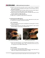
8.3
Rotor Casing, Rotor
a
)
When replacing the main bearings and the side bearings, put shrink fit on the inner-ring
with the rotor.
b
)
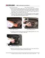
Apply oil on the bearing outer-ring inserted in the bearing head and the bearing
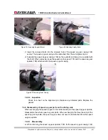
inner-ring attached to the rotor. Install the M rotor into the rotor casing first. With the use
of chain blocks (etc.), suspend and the balance the rotor with a nylon sling. When the
rotor is half-way in the casing, remove the suspension and push it in.
c
)
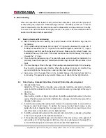
On the teeth tip of the F rotor suction side, there number
①
,
②
are stamped. Turn the
rotor so that these stamps face the M rotor side.
d
)
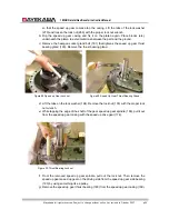
Suspend the F rotor. Place the M rotor so that the tooth that has the
①
stamped faces
the F rotor side.
e
)
Place the tooth with the
①
stamp of the M rotor between the
①
,
②
teeth of the F rotor,
and insert the F rotor half-way. Then remove the nylon sling. Push the rotor all the way
in.
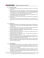
8.4 Suction
Cover
a
)
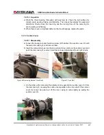
Install the side bearings. Like the main bearings, the side bearings are
すき間
fitted. Do
not tilt them. When it is difficult to install the side bearings as it is tilted, put a pad and tap
it to straighten it.
b
)
Place the lubricating ring in the way where the nozzle faces the bearing, and hold it with
the stop ring. Make sure the oil discharge holes are vertically aligned.
c
)
Push the unloader slide rod towards the unload position, and expose the half of the
unloader slide rod from the rotor casing.
d
)
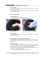
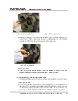
Match the unloader slide rod and the hole on the suction cover. Slide the suction cover
on the platen close to the rotor casing.
e
)
Match the positions of the side bearing and the rotor shaft, and put them together by
pushing them in parallel to the shaft.
f
)
Hammer the set alignment pins in, and tighten the hexagon socket head screws. To
tighten the hexagon socket head screws, evenly tighten the bolts in diagonal. Use a
torque wrench to tighten with a proper torque in the end.
g
)
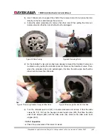
Move the unloader slide rod to the direction of the shaft to check the movement of the
unloader slide valve and the Variable Vi slide valve. Then softly turn the M rotor by hand
to make sure that the rotor turns.
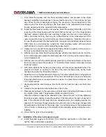
8.5 Thrust
Bearings
a
)
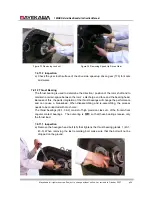
If the disassembled thrust bearing is to be installed as disassembled, install it in the
same direction as that of the thrust adjusting washer and the spacer of the M/F rotors
when they were removed. Special care is required so that the journal area of the tip of
the M rotor will not be damaged.
b
)
When the washer or the thrust adjusting washer has foreign objects in them, the
measurement of the same thrust bearings can change. The inaccuracy in the
measurement will prevent the adjustment of the end clearance. Make sure to keep any
foreign objects away from the parts.

