Page 20
USING THE LENGTH STOP
WARNING Before performing any
assembly or adjustment, always
disconnect from power source. Failure
to unplug your saw could result in
accidental starting causing serious
injury.
WARNING To avoid risk of personal
injury, if movement is tight or if there is
play in the adjustment, have your saw
serviced by an authorized service
center before using or contact (866)
902-9690 for assistance.
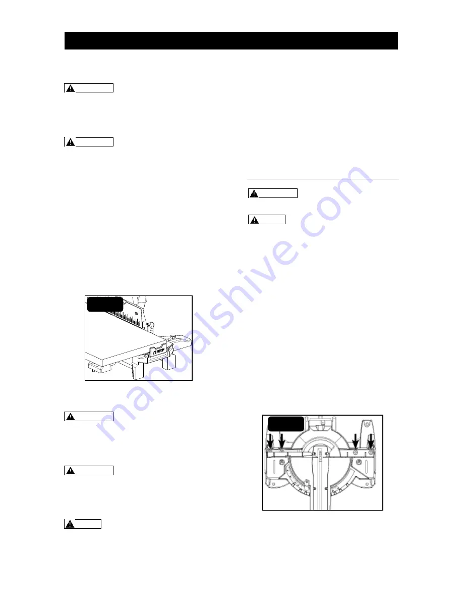
It is very convenient to get all same length
work pieces by using the length stop. This
length stop is located on the extension
arms (Fig. 20).
The length stop is a pivoted block. To
using the length stop, press the lower part
of its side face. It will turn to form a right
angle to the table.
To fold the length stop, gently push the
upper part of it toward saw arm. It will
return to original position.
ACCURACY ADJUSTMENT
WARNING Before performing any
assembly or adjustment, always
disconnect from power source. Failure
to unplug your saw could result in
accidental starting causing serious
injury.
WARNING To avoid risk of personal
injury, if movement is tight or if there is
play in the adjustment, have your saw
serviced by an authorized service
center before using or contact (866)
902-9690 for assistance.
NOTE: The saw is factory set for
accurate cutting. After assembling it,
check for accuracy as directed in the
following section of this manual. If
shipping has influenced the settings,
refer to specific procedures explained
as following.
There are 5 accuracy adjustments totally:
(1) Squaring the blade to the fence.
(2) Squaring the blade to the table.
(3) Adjusting the blade to the miter table,
45° bevel, 0° miter.
(4) Bevel angle indicator adjustment.
(5) Miter angle indicator adjustment.
(1) SQUARING THE BLADE TO
THE FENCE
WARNING Failure to unplug your
saw could result in accidental starting
causing serious injury.
NOTE: To do accuracy adjustment,
you will need the combination square
(not supplied).
Step 1: Unplug the saw.
Step 2: Set the bevel and miter angles to
0°.
Step 3: Lower and lock the saw arm in the
“Down” position.
Step 4: Place the heel of a combination
square against the blade body (not teeth)
and the ruler of the square against the
fence.
Step 5: If the blade is not 90° to the fence,
completely unscrew the fence-locking knob
and remove the upper sliding fences.
Step 6: Loosen four screws with hex key
(not supplied) and rotate the fence until the
square ruler is flush along its entire length.
Retighten the hex-head bolts (Fig. 21).
Step 7: Replace the upper sliding fences
and reattach the fence-locking knobs.
FIG. 20
FIG. 21
ASSEMBLY AND ADJUSTMENT


