Paragraphs
38-40
stalled facing camshaft. s1de of engine.
Replacement rods are not marked but
should be stamped with cylinder number
before installation, on side of rod op·
posit.e the oil spray hole. Piston skirts are
notched at lower edge; notch is to be in·
stalled to f1·ont of engine when unit is
reassembled.
Tighten the connecting rod cap screws
to a torque of 54·61
N ·
m (40-45
ft
.
.
lbs.).
PISTONS, SLEEVES AND RINGS
All Gasoline Models
38. Pistons are available in standard
size only, and are available only in a kit
which includes piston, pin, rings and
sleeve for one cylinder. Piston is cam
gl"OUnd.
If piston and/or sleeve are scored, if
piston ring grooves or pin bore are worn
or damaged, or
if
cylinder wall taper ex·
ceeds
0.20 mm (0.008 inch), renew piston
and sleeve assembly.
Piston ring kits
are
available separate
ly. Kits are marked for correct piston
ring installation. Refer also to Fig. 39 for
correct installation of rings.
Recommended piston ring end gap is
0.25·0.50 mm (0.010·0.020 inch) for all
rmgs. Recommended side clearance in
ring
groove
is 0.09·0.13
mm
(0.0035·0.0050 inch) for top ring;
0.09·0.14 mm (0.0035·0.0055 inch) for
second and third compression rings.
Renew piston and sleeve assembly
if
side
clearance of top ring exceeds 0.19 mm
(0.0075 inch), or 0.20 mm (0.008 inch) for
second or third compression rings.
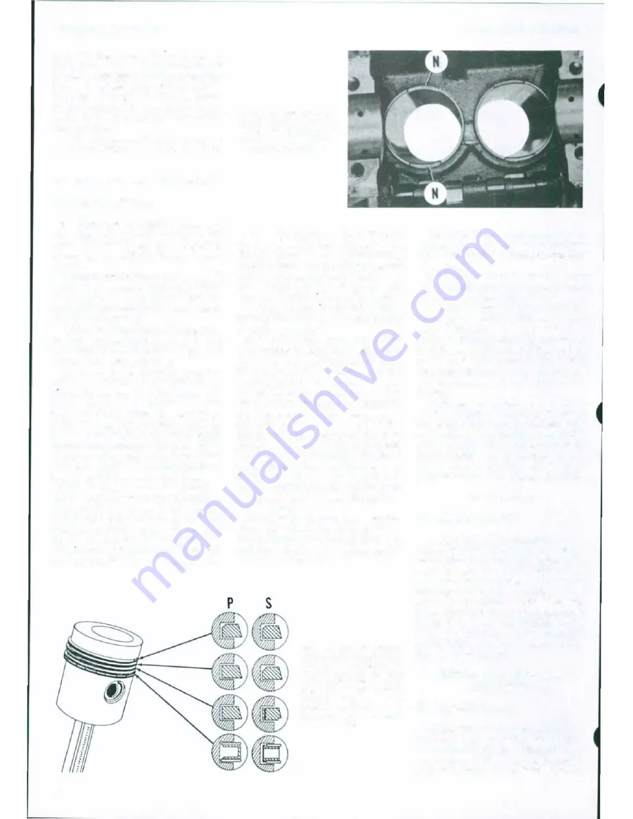
Refer to Fig. 39 for installation of
piston rings in grooves. The piston rings
shown at
(P)
are for use in new sleeves,
and l"ings (S) are for service in worn
sleeves.
Th
install rings (P) for new
sleeves observe the following: The top
ring
IS
chrome plated, taper faced and
may have inside diameter beveled. The
22
Fig. 40-Notches (N) In bot·
tom of sleeves are tor con·
nectlng rod c/ear��nce and
should
be
at right angles to
cr��nkshaft as shown.
side of ring marked by dot or by bevel
cut away should be toward top of piston.
The second and third compression rings
are taper faced and should be installed
with side marked by dot toward top. In·
stall oil ring expander in groove first,
then install rails w1th gaps 50 mm (2 in·
ches) from the gap
m
expander. Gap in
one rail should be to left., other to right
of
gap in expandet·.
'Ib
install rings (S) for use in used
cylinder sleeves, observe the following:
The chrome plated top ring is taper
faced. Install top ring with dot or bev·
eled inside diameter toward top of piston.
The second compression ring should be
installed with beveled inside diameter
or dot toward top. The third compression
ring should have expander behind ring
and the relief cut into outside diameter
of ring should be down. The expander for
the bottom oil control ring should be in·
stalled first, followed by the two rails.
One rail should have end tap 50
mm
(2
inches) to left of expander ends, the other
rail should have end gap 50 mm (2 in·
ches) to right.
The cylinder sleeves have notched
reliefs at bottom for connecting
rod
clearance. The relief notches should be
at right angles to crankshaft centerline
as shown in Fig. 40.
Fig. 39-Draw/ng showing
cross·sect/on of rings show·
lng COffiiCt Installation.
Pro·
duct/on rings (P) are used
with new sleeves and service
rings (S) are Installed In
sleeves which have been
used.
II
ring Is marked with
dot, the dot should
be
toward
top.
MASSEY -FERGUSON
Use a suitable puller to remove the wet
type cylinder sleeves. Clean all surfaces
of cylinder block which contact sleeve or
sleeve seals.
Install sleeve into cylinder block bore
before installing any seal rings to check
for sleeve standout <Fig. 41). Select the
necessary thickness
of
shims to provide
0.03·0.10 mm (0.001-0.004 inch) stand·
out. Measure distance
using a
straightedge and feeler gage and be sure
that sleeve is fully seated without nicks,
burrs or foreign material preventing
complete installation. Excessive or insuf·
ficient standout will both cause water
leakage.
After sleeve standout has been
checked, install sealing rings at bottom
of sleeves. Make sure that seal rings are
not twisted, then lubricate seals with
petroleum jelly. Press sleeves into place
being careful not
Lo
damage or lose
shims. Notches (N-Fig. 40) should be
perpendicular to crankshaft
as
shown.
PISTON PINS
All Gasoline Models
39. The full floating piston pins
are re
tained in piston bosses by snap rings.
Piston pins
are
available in standard size
and 0.08 and 0.13
mm
(0.003-0.005 inch)
oversizes. Recommended clearance for
piston pin in both the connecting
rod
and
piston is 0.005.0.015 mm (0.0002-0.0006
inch
).
Standard piston pin diameter is
21.821-21.826 mm (0.8591-0.8593 inch).
Hone new bushings to 21.831-21.836
mm (0.8595·0.8597 inch) after installa
tion in connecting
rod.
CONNECTING RODS AND
BEARINGS
All Gasoline Models
40.
Connecting
rod
bearings
are
of the
precision type, renewable from below
after removing oil pan. When installing
new bearing shells, make sure that the
projection engages the milled slot in rod


