Paragraphs
21 0-212
bracket, and can be removed afler
removing lifl cover as outlined in
paragraph 207.
To dt
sasse
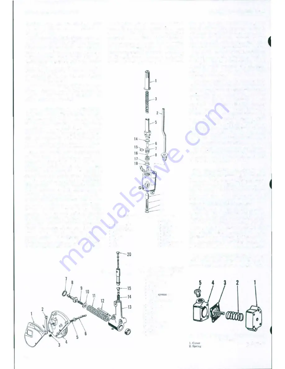
mble the dash pot, loosen ad·
justing screw (18-Fig. 195) and remove
adjustment rod (20) and spring (19). In·
vert the housing and remove plunger
(17), needle (15) and spring (14). Depress
piston rod and guide (8) and remove snap
ring (7), then remove spring (9), piston
(1 0) and spring (11). Expansion pi ugs or
guide (12) can be removed from body if
renewal is indicated.
Assemble by reversing the disassem·
bly procedure using Fig. 195 as a guide.
Adjust as outlined in paragraph 200
after tractor is assembled.
210.
PRESSURE CONTROL
VALVE AND DIAPHRAGM.
The
pressure control valve shown exploded
in
Fig.
196
serves the dual purpose of
providing pressure relief for the main
hydraulic pump during normal opera·
tion and providing weight transfer for
added traction when using some types
of pulled or mounted implements.
Pressure line (2) is connected to weld·
ed tee-block in standpipe, and ram
cylinder pressure acts against. servo
piston (7) which is held closed by the
variable rat.e spring
(3).
The spring is
compressed
to
the maximum when inner
quadt·ant control lever
is
in "POSITION
CONTROL"
or "CONSTANT
PUMP
ING"
position, and is released at a
uniform rate as lever is moved to low
end of
"P
R
E
SS
U
R
E CONTROL"
sector
of quadrant. When pressure valve
ts
cor·
rectly adjusted and operating properly,
pressure in the ram cylinder circuit
should be 140-275 kPa (20-40 psi) with
inner quadrant control lever at extreme
"LOW" end of quadrant and should in·
crease at.
n
steady rate as lever is
moved, until the specified reliefpressut·e
is obtained as lever moves into
"CONS
TANT PUMPING"
sector of Quadrant.
The servo piston (7) and matched
sleeve (8) connect the control dtaphragm
assembly (Fig. 197) to control
passage
of
pressure valve. When servo piston is
against stop pin in valve body (9-Fig.
196) the diaphragm passage is open
to
open to reservoir. As pressure builds up
in lift cylinder circuit. and piston (7)
moves upward against. spring pressure,
- 9
10
I I
1 3
1 2
Fig. 196-E'IIploded view of p,.ssure control valve.
I
A<IJUI!ting tube
2
Pre
ssu
r
e tube
3 Prell!lure apnng
6 Ptlol
6
Plunger
7 Cutde
8 &,at
9
Bod)
10 Val••
II
Spronw
12 Snop
nn11
13 w ..
hcr
H
Spring
16 "o·· ra
ng
l6
Ball
17 Boek up wn•hor
18 "0'' rani(
-
19
18�
_11
Fig. 195-Draft responn
dashpot,
control cover
and
usocleted
parts.
80
J
Control
CO\'tr
2
Rc��:pon,.,.
lt-\lfr
3 i'ort plu11
4
S1de covt\r
5
Sprln�
8
Oran
ro
cam
7 Snep TlnK
8.
Plun�o·r
&
bu•h•ng
9
Spron11
10 Olt•hpot p••w
n
II
Spnn11
12 Cu•clt
13 Oa•hpot
14
Spnna
15 Reoponk n<t'dl�
17 Val•e plun�!ef
18.
A<IJusung "'"""
19
Sprona
20 NL-t-dlt'
MASSEY -FERGUSON
the diaphragm exhaust passage is
closed. When the pressure Jjmit is
reached, fluid passes servo piston to
diaphragm passage, extending the
diaphragm plunger to move the main
hydraulic pump control arm to neutral.
Relief valve (10) is preset at a slightly
higher pressure than diaphragm return
spring (2-Fig. 197). The valve provides
a safety relief passage if diaphragm
plunger malfunctions or system
is
im
properly adjusted.
To disassemble the pressure control
valve, refer to Fig. 196 and proceed as
follows: Withdraw adjusting
tube
(1)
and
sprmg
(3),
then unscrew and remove
pilot (5). Using needlenose pliers,
carefully withdraw guide
(7).
Remove
piston seat (8) using a hooked wire.
Relief valve (10) and spring
(11)
can be
removed after removing snap ring (12).
Guide (7) and seat (8) ate available on
ly as a matched set. All other parts are
available individually. Examine all
parts carefully and renew any which
are
worn, scored or damaged.
Assemble the pressure control valve
by reversmg the di
sasse
mbly procedure.
Adjust as outlined in paragraph 199
after lift cover is reinstalled.
211.
INTERNAL UNKAGE AD
JUSTMENT.
The following internal lin.
linkage adjustments must be performed
before reinstalling lift cover. lnvert the
lift cover in a fixture or on a bench.
Block up the cover as necessary so
rockshaft can be moved to the normal
raised "TRANSPORT" position.
Check and adjust master control
spring (5-Fig. 192) as outlined in
paragraph 194. Make sure draft control
rod does not contact spring plunger
when adjusting master control spring.
Move draft control lever to fully lowered
position on quadrant and, if
n
ece
ss
ary
,
place a wedge between lift cover casting
and draft control rod adjusting screw
.
212. D
R
AFT
CONTROL ROD.
To ad
just drafl control rod (6-Fig. 198), first
move drafl control lever
to
full
"UP"
Fig. 197-E'IIploded view of pressure control
dlaphregm.
3. Otaphra�m
4.
Body


