SERVICE MANUAL
If
"E" mark is slightly out of align
ment with end of snap ring, the mount
ing holes in pump flange are elongated
to permit minor timing variations. If it
is necessary to move pump, check align
ment of timing marks on pump flange
and timing gear case (Fig. 96) and scribe
new lines as necessary. If "E" mark can
not be aligned by shifting pump on
mounting studs, either the No.
1
piston
is not on compression stroke or engine
timing gears are not Limed correctly.
99. REMOVE AND REINSTALL.
The injection pump drive shaft has a
milled slot (S-Fig. 98) in forward end
which engages the dowel pin CD-Fig. 97)
in pump drive gear. The injection pump
drive gear cannot become unmeshed
from idler gear with timing gear cover
in place. Therefore, injection pump can
be removed and reinstalled without
regard to timing position.
Before removing the injection pump,
thoroughly wash the pump and fuel line
connections. Immediately plug all open
ings
in fuel system as lines are
discon
nected to prevent entry of dirt.
Disconnect throttle rod (Fig. 93) and stop
cable or rod from pump. Shut ofT fuel,
then disconnect fuel inlet, return and
high pressure lines from pump. Remove
inspection cover from front of timing
gear cover, then remove three cap screws
attaching injection pump drive gear to
pump shaft. Remove pump flange stud
nuts, then withdraw pump.
'Ib
reinstall pump, align milled slot
(S-Fig. 98) in pump shaft with dowel
CD-Fig. 97) and insert pump. Align tim
ing marks (T-Fig. 96) on pump flange
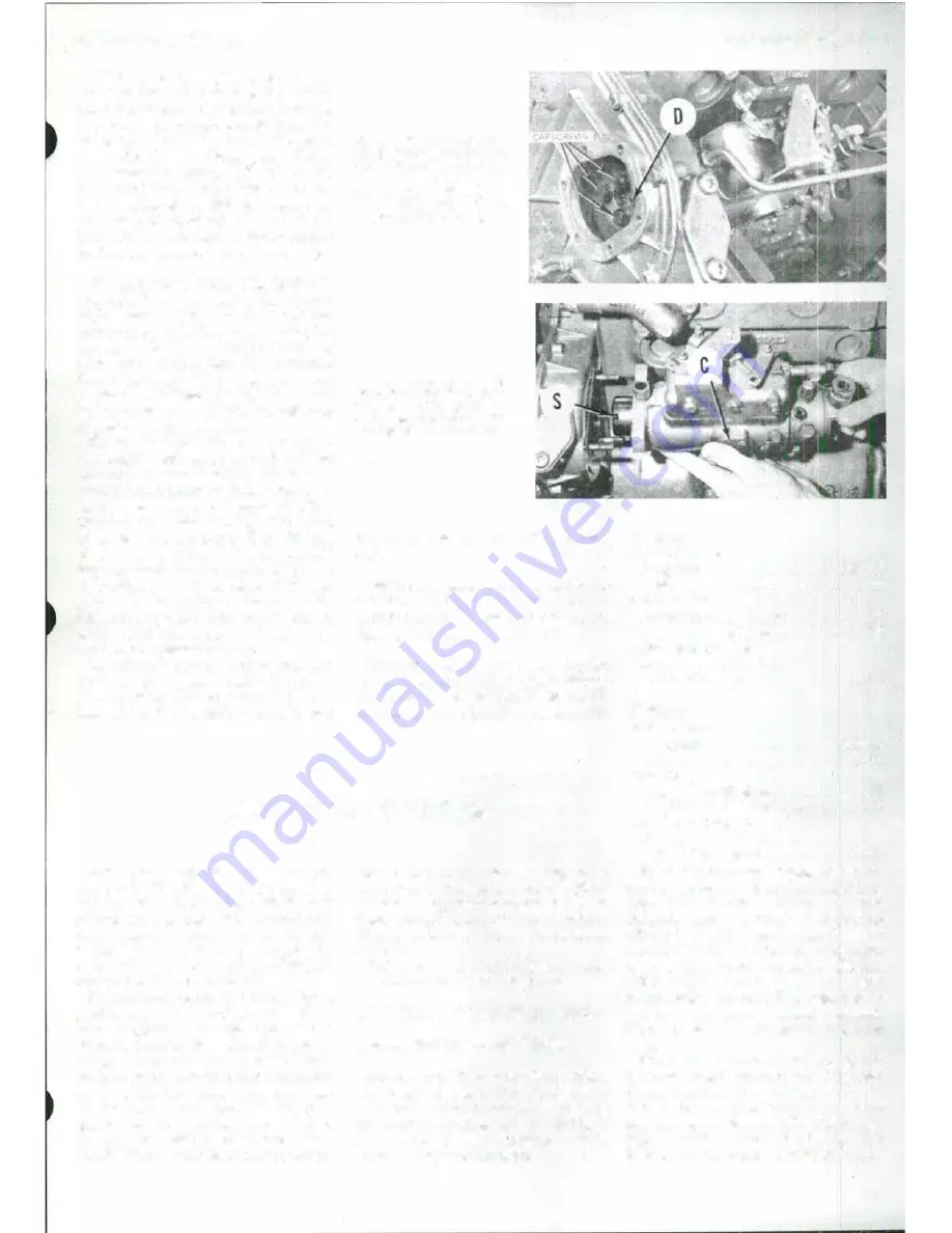
Fig. 97-To remove Injection
pump, It Is first necessary to
remove Inspection cover and
remove three retaining cap
screws lrom drive gear.
Dowel (D) engages slot In
pump shaft (Fig
.
98).
Fig. 98-Locatlng slot (S)
must align with dowel (D
Fig.
97)
when pump Is
reinstalled. Pump timing win
dow cover Is shown at (C).
and timing gear case, then tighten stud
nuts.
NOTE:
Pump can only
be
Installed In one
position. If timing gear train
has
n
o
t been
disturbed and timing marks (T-Fig.
96)
are
aligned, timing should
be
correct.
Complete installation by reversing the
removal procedure. Check pump timing
as outlined in paragraph 98. Bleed air
from system as outlined in paragraph 86.
..
ELECTRICAL SYSTEM
100. The electrical system on all
models is 12 volt, negative grounded
system. Models MF230, MF235 and
MF245 are equipped with Delco-Remy
alternator and starter motor. Models
MF240 and MF250 may be equipped
with either Lucas or Perkins· (Hitachi)
alternator and starter motor.
Before any electrical system service is
performed, a thorough check of condition
of battery, cable connections, alternator
drive belt and pulleys should be made.
Always disconnect battery leads before
pe1forming any service operations on the
tractor electrical system. Do not connect
or disconnect any part of charging
system while the engine is running
as
damage to voltage regulator could
result. When connecting- batten' leads.
booster battery or battery charger, be
sure to observe correct
polarity
(positive
to positive, negative to negative). Do not
short across or ground any terminals on
alternator. Do not attempt to polarize
alternator.
Refer to appropriate Figs. 247 through
250 for tractor wiring diagrams.
ALTERNATOR AND REGULATOR
Models MF230-MF235-MF245
101.
TESTING.
A Delco·Remy alter
nator with integral solid state regulator
is used on these tractors. Both 37 amp
and 42 amp alternators are available, so
be sure of model when testing. Refer to
the following specifications:
Paragraphs
99·1 01
1100578
Field Current
Amperes . . . . . . .
.
.
.
. .
. . .
.
.
.
4.0-4.5
Volts
.
. . . . . . . . . . . . . . . .
.
.
.
. . . .
12
Cold Output
Amperes at 2000 rpm . . . . . . . . . . 22
Amperes at 5000 rpm
. . . • . . . . . .
33
Rated Hot Output
(Amperes) at Maximum
Operating Speed . . . . . . . . . . . . . 37
1100583
Field Current
Amperes
.
.
.
. .
.
.
. . .
.
.
. .
.
.
. .
4.0-4.5
Volts . . . . . . . . . . . . . . . . . . . . . . . .
1
2
Cold Output
Amperes at 2000 rpm .
.
.
.
.
.
.
. . .
25
Amperes at 5000 rpm . . . . . . . . . . 37
Rated Hot Output
(Amperes) at Maximum
Operating Speed . . . . . . . . . . . . .42
'Ib
test alternator output while in
stalled on tractor, fll'st disconnect bat
tery ground cable. Connect a test
ammeter and voltmeter in circuit at
alternator "BAT" terminal
as
shown in
Fig. 99. Connect a carbon pile
across bat
tery as shown and tw·n on headlights.
With engine operating at moderate
speed, adjust carbon pile as required to
obtain maximum current output.
Voltage should be approximately
14.5
volts.
If ampere output is within 10 amperes
of rated output stamped on alternator
frame, alternator is not defective.
If
out
put is not within 10 amperes of rated
output, ground field winding by insert
ing a screwdriver into
test
hole (Fig.
100)
in rear of alternator. If output is now
41


