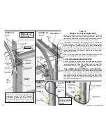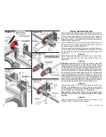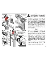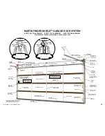
FIGURE 15 ONE TORSION-SPRING ASSEMBLY
TURNS ON TORSION SPRINGS TO BALANCE DOOR
WITH *STANDARD CLEARANCE OR LESS
DOOR
HEIGHT
4“ (102)
CABLE DRUM
5 1/4“ (133)
CABLE DRUM
8“ (203)
CABLE DRUM
7’ (2130)
8’ (2440)
9’ (2740)
10’ (3050)
11’ (3350)
12’ (3660)
13’ (3960)
14’ (4270)
15’ (4570)
16’ (4880)
17’ (5180)
18’ (5490)
19’ (5790)
20’ (6100)
8-9
9-10
10-11
11-12
12-13
13-14
6-8
7-9
8-10
8-10
9-11
10-12
11-13
11-13
12-14
13-15
9-11
13-15
10-12
*SEE SUPPLEMENTS D AND E FOR HIGH-LIFT OR VERTICAL-LIFT
STEP 20
TORSION SPRING ASSEMBLY
Observe the
red
and
black
color codes on the spring winding
cones and cable drums and assemble correctly. All references to
right or left are viewed from inside looking out through the door
opening.
ATTENTION: If the torsion spring(s) are reversed
and fastened on the wrong side, they will back-wind. The door
will only open part way and stop.
Put the torsion spring assembly together on the floor for one or two
torsion springs as provided. Do not fasten torsion tubes together in
coupler until installed above the door. (See Figure 17D) Fasten
the spring anchor cones to the side spring anchor brackets. (See
Figures 15,16) Extra heavy doors may have four springs
provided.(See Supplement F)
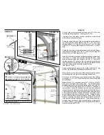
For easy side spring anchor bracket assembly to the lock-on side
bearing brackets at the end of STEP 23, two 3/8“ x 1” short neck
carriage bolts are fastened to each side spring anchor bracket with
3/8” lock nuts. The 3/8“ lock nuts also act as necessary spacers for
the wider 4" cable drums used on doors higher than 8' (2440).
(See Figures 18A,18B)
NOTE: Single and double wide doors may have one or two springs
as provided. A single torsion spring, on a one torsion spring
assembly, may have a
red
or
black
spring winding cone. If
red
,
the torsion spring is right wound and will be assembled on the right
side. If
black
the torsion spring is left wound and will be assembled
on the left side.
The
red
cable drum is assembled on the left side. The
blac
k cable
drum is assembled on the right side. The torsion tube furnished is
at least 4“ (102) longer than the length between the side bearing
brackets. (See Figures 15,15A,16)
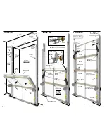
DOORS WITH ONE PIECE TORSION TUBE
Lift
the torsion spring assembly up and slide the torsion tube into
each lock-on side bearing bracket. Flex torsion tube as needed.
(See Figure 15, 17A,17C)
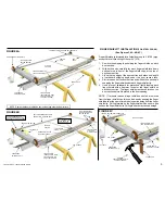
FIGURE 15A
LEFT
RIGHT
LEFT WOUND
SPRING
RIGHT WOUND
SPRING
ONE PIECE TORSION TUBE FOR
DOORS UP TO 10’2“ (3100) WIDE
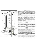
FIGURE 16 ONE/TWO TORSION-SPRING ASSEMBLY
TW PIECE TORSION
TUBE, WITH COUPLER,
FOR DOORS OVER 10’2“
(3100) WIDE
O
CENTER BEARING BRACKET
(Wide doors furnished with two)
RIGHT HALF
TORSION TUBE
TORSION SPRINGS
3/8“ X 1” SHORT NECK
CARRIAGE BOLT
3/8“ LOCK NUT
TORSION SPRINGS
3/8“ LOCK NUT
3/8“ X 1” SHORT NECK
CARRIAGE BOLT
TORSION TUBE
SIDE SPRING ANCHOR BRACKET
SPRING ANCHOR CONE
SIDE SPRING ANCHOR BRACKET
SPRING ANCHOR CONE
BLACK
SPRING
WINDING
CONE
RED
SPRING
WINDING
CONE
SIDE SPRING
ANCHOR BRACKET
3/8“ X 1” SHORT
NECK CARRIAGE BOLT
COUPLER
3/8“ X 1” SHORT NECK
CARRIAGE BOLT AND 3/8“ LOCK-NUT
SIDE SPRING
ANCHOR BRACKET
LEFT HALF TORSION TUBE
Do not fasten torsion tubes together in the coupler
until installed above the door (See Figure 17D)
WAR I G
N N
A N
W R ING
W R
NG
A NI
WARNING
N
G
WAR IN
WARNING
WARNING
WARNING
WARNING
WARN G
IN
WARNING
WARN G
IN
CENTER
BEARING
BRACKET
CENTER
BEARING
BRACKET
ATTENTION! Springs can be damaged by
dropping on or throwing against sharp objects.
This may result in reduced spring life.
13
COPYRIGHT © 2004 MARTIN DOOR
RED
RED
SPRING WINDING CONE
CABLE DRUM
BLACK
CABLE DRUM
BLACK
SPRING WINDING CONE
BLACK
SPRING WINDING CONE
RED
CABLE DRUM
RED
SPRING WINDING CONE
BLACK
CABLE DRUM


