background image

11

HORIZONTAL

TRACK

3/8“ X1”
SHORT 
NECK
SAFETY 
BOLT
AND 3/8“
LOCK 
NUT

FIGURE 13

A

B

ABOUT

8 1/2“ (216)

ABOUT

8 1/2“ (216)

A
B

FIGURE 13C

FIGURE 13B

LEVEL

HORIZONTAL TRACKS

HORIZONTAL TRACK ANGLES

FLAG

ABOUT
8 ½“ (216)

SPLICE
PLATE OR 
SPLICE 
BRACKET

TOP DOOR
SECTION

LOCKING
PLIERS

VERTICAL
TRACK

RA OR RB 
SHIELD

PUNCHED ANGLE
(OPTIONAL)

3/8“ X 1” SHORT
NECK CARRIAGE BOLTS
AND LOCK NUTS

FIGURE 13A

(ALSO SEE STEP 16)

¼“ LOCK
NUTS

FLAG

RA OR RB
SHIELD

STEP


17

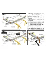
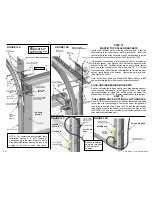
The top of the vertical tracks should be about 8-1/2“ (216) down 
from the top of the closed door. (See Figures 13,13A)

If working alone, use a ladder or use a rope tied to a rafter to hold 
up the back of the horizontal track.

Fasten the curved front end of the left and right horizontal tracks to 
the splice plates or splice brackets with 1/4" X 1/2" short neck 
carriage bolts and 1/4" lock nuts. (See Figures 13, and 13A) See 
Figure 13AA   for splice   plate extension for doors over 12’ (3660) 
high.

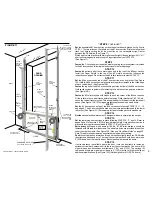
Fasten the front of the horizontal track angle to the top of the flag or 
reverse bracket shields with a 3/8" X 1" short neck carriage bolt 
and a 3/8" lock nut. (See Figures 14A,14B)

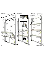
Level the horizontal tracks and set them parallel and square back 
from the door.   Fasten the horizontal tracks at the back, using 
optional punched angle track hangers with 3/8" X 1" short neck 
carriage bolts and 3/8" lock nuts. One of the bolts must go through 
the back of each horizontal track as a safety bolt to prevent the top 
roller from rolling out the back of the horizontal track.
(See Figures 13,13B)

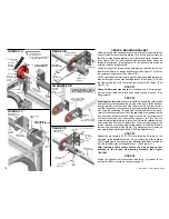
Fasten optional punched angle to the ceiling with 5/16" X 2” lag 
screws.   Do not fasten a punched angle brace until STEP 27. 

Make sure the curved front ends of the horizontal tracks and the 
vertical tracks line up. Tighten the remaining bolts and nuts.

Doors over 14' (5270) high or any horizontal track that deflects 
more than 1/2" (13) in 10' (3050) should also be center hung with 
punched angle.

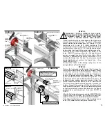
Note

:   Martin 2" (51) horizontal tracks, for 7' (2130) to 14' (4270) 

high doors, are made with slotted holes.   The horizontal track 
angles are fastened to the horizontal tracks slotted holes with 1/4" 
X 1/2" short neck carriage bolts and 1/4" lock nuts.   If needed, to 
remove stress, loosen the bolts and nuts and move the horizontal 
tracks or horizontal track angles, then re-tighten the bolts and nuts.   
This procedure can also be used to slightly raise or lower the back 
of the horizontal tracks to miss an obstruction or provide a more 
perfect balance to the door in the open position.   Raising the back 
of the horizontal tracks will help to reduce the open door spring 
tension.   Lowering the back of the horizontal tracks will help to 
increase the open door spring tension.   The above procedure of 
raising or lowering the back of the horizontal tracks, to improve the 
open door balance, is sometimes used by professional installers, 
only after completing STEP 26.

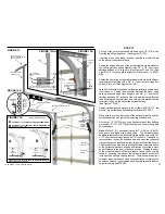
FIGURE 13AA

¼“ LOCK

NUTS

¼“ X ½” SHORT
NECK CARRIAGE
BOLTS

FLAG

SPLICE PLATE EXTENSION FOR ALL DOORS

OVER  12’  (3660)  HIGH AND  HI-LIFT DOORS 

                 WITH T-LOCK HANDLE 

OPTIONAL 3“ (76) VERTICAL TRACK EXTENSION KIT


OPTIONAL 6“ (152) VERTICAL TRACK EXTENSION KIT


-Can be cut to 3” (76)

EXCEPT MO, SP, OR SL DOORS.

EXTENSIONS OK TO USE WITH REGULAR FURNISHED HARDWARE

COPYRIGHT © 2004 MARTIN DOOR

¼“ X ½” SHORT
NECK CARRIAGE
BOLTS

ABOUT
8 ½“ (216)

SPLICE PLATE OR
SPLICE BRACKET

Содержание MARTIN FINGER SHIELD

Страница 1: ...pletely weather seal this door Vent according to local building codes CAUTION Low levels of carbon monoxide in the garage and home can cause headaches and flu like symptoms Additional venting may be r...

Страница 2: ...s for fastening the punched angle are furnished with the door hardware fasteners 1 2 3 4 5 6 7 8 9 10 11 12 13 14 15 16 17 18 19 2 3 6 7 7 8 9 WAX LUBE 0 1 40 M TO O R I O L DOORS UP TO 9 2740 HIGH IN...

Страница 3: ...ENING INFORMATION Measurements shown are with 4 102 cable drums and 2 51 tracks See supplement B page 19 for other clearances and modifications FIGURE 1 FIGURE 2 FLOOR FLOOR CEILING HEADER WALL WALL H...

Страница 4: ...ng screws go through the lock on bottom roller bracket the bottom reinforcing angle the inside return of the steel door section and fasten tight into the 1 8 holes in the steel or wood stile See Figur...

Страница 5: ...same time it is being pulled away from the finger shield clip Pulling forward on the finger shield will cause it to grip solid on the finger shield clip Pulling too hard may cause damage FIGURE 4B FIG...

Страница 6: ...e furnished for the door sections on steel residential doors 20 3 6172 to 24 2 7370 wide This width door includes double end stiles double roller brackets with hinges and long stem rollers See Figures...

Страница 7: ...ce all doors are furnished with RA or RB Shields They fasten solid to most flush surfaces including wood concrete brick block not RB Shields drywall tile stone steel etc Each fastener adds strength to...

Страница 8: ...strips placed to level the door section in STEP 1 See Figure 9 Wood Jambs Drill 1 8 3 holes then fasten with 5 16 x 2 lag screws Steel Jambs Drill 1 4 6 hole Fasten with 5 16 x 3 4 self tapping screws...

Страница 9: ...rovided to fasten packet to wood doors STEP 14 Decide optional window placement Adesigner window is normally a top section STEP 15 Set the remaining door sections in place following STEPS 10 11 and 12...

Страница 10: ...DOOR SECTION 4 DOOR SECTION 2 ROLLER BRACKET AND HINGE LIFT HANDLE ROLLER AND ROLLER SHIELDS 2 DOOR SECTION 1 DOOR SECTION 1 ROLLER BRACKET AND HINGE LIFT HANDLE INSTRUCTION MANUAL PACKET INSTRUCTION...

Страница 11: ...gle to the ceiling with 5 16 X 2 lag screws Do not fasten a punched angle brace until STEP 27 Make sure the curved front ends of the horizontal tracks and the vertical tracks line up Tighten the remai...

Страница 12: ...the rope strap See Figure 14C Fasten the other end of the pull down rope to the bottom roller bracket See Figure 14D WARNING To help protect children do not fasten pull down rope to an electrically op...

Страница 13: ...orsion spring is right wound and will be assembled on the right side If black the torsion spring is left wound and will be assembled on the left side The red cable drum is assembled on the left side T...

Страница 14: ...rum slot Wind the remaining lift cable onto the red cable drum by hand carefully following the groove Push the red cable drum against the left lock on side bearing bracket and tighten the two 3 8 set...

Страница 15: ...be too heavy If additional torsion spring adjustment is made follow the procedures and cautions outlined in STEP 25 Add or delete 1 4 turn at a time alternating torsion springs Recheck the balance Re...

Страница 16: ...28 Note Doors over 14 5270 high and any extra heavy door that causes the horizontal tracks to deflect more than 1 2 13 in 10 3050 should also be center hung and braced with punched angle to support th...

Страница 17: ...STALLED RAIN SHIELD INSTALLING RAIN SHIELD BEFORE THE DOOR IS INSTALLED a Complete numbers 1 3 4 5 and 6 above b If re packaging the door make sure each Finger Shield properly fits under the Rain Shie...

Страница 18: ...are repaired the same except they require more time to remove the back After the repair the back is replaced and riveted CAUSES During a lifetime various accidents can cause a dent including bicycles...

Страница 19: ...ace the end stiles with new rivets INCREASE DOOR HEIGHT 2 1 2 64 1 Use rivets or screws to fasten finger shield clips to the top of the top door section 2 Snap a Finger Shield into the finger shield c...

Страница 20: ...s explained in STEP 18 also Figures 14A and 14B Fasten the front of the low clearance tracks above the horizontal tracks to the third hole of the horizontal track angle See Figure C1 Fasten the back o...

Страница 21: ...8 SPRING ANCHOR BRACKET SPLICE PLATE OR SPLICE BRACKET LOCK ON SIDE BEARING BRACKET TORSION TUBE BLACKCABLE DRUM LOCK ON SIDE BEARING BRACKET FLAG TOP ROLLER BRACKET ROLLER AND ROLLER SHIELD LOW PROFI...

Страница 22: ...shed for 5 section high doors etc See FIGURE 6 C Doors over 14 2 4320 wide are furnished with five 3 76 U struts for 4 section high doors fastened same as B above plus extra struts are installed on lo...

Страница 23: ...KET FOR OWNERS DOOR AND OPENER INSTRUCTION MANUALS 2 DOOR SECTION 3 DOOR SECTION 4 DOOR SECTION TOP DOOR SECTION FOR OPTIONAL 3 6 51 102 TRACK EXTENSIONS SEE PAGE 11 FOR OPTIONAL SIDE LATCH SEE PAGE 1...

Страница 24: ...nishing process When a steel door is installed and in the closed position paint the outside surface of the door only It is not necessary to paint the door sections on the edges joints and inside like...

Отзывы: