12
STEP 18
MARTIN TOP ROLLER BRACKETS
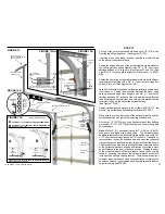
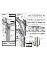
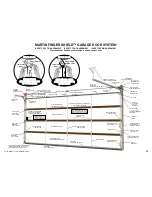
Loosen the bolts and nuts on the top roller brackets. Slide the
roller shaft into the roller tube of each roller bracket. Insert the
roller into the curve of the horizontal track. The roller tube is on the
bottom side of the top roller bracket. (See Figures 14A,14B)
If the top door section has a strut, place the strut on or under the
top roller bracket. (See Figures 14A,14B) Fasten each top roller
bracket to the stile. For added strength on heavy doors, fasten
each top roller bracket to the stile with extra 1/4" X 1” thread
forming screws. Adjust the top roller bracket so that the top door
section lightly touches the header. Tighten the bolts and nuts.
(See Figures 14A,14B)
Note: If steel door includes a Martin Side Mount Opener, install
opener door bracket now. See Opener Instruction Manual.
LOCK-ON SIDE BEARING BRACKETS
Rotate and fasten the left and right lock-on side bearing brackets
to the horizontal track angle. (See Figure 14A,14B) The center
line measurement in Figure 14B should match the center line
measurement in Figure 17B. (Fasten vertical and solid to jambs.)
STEP 19
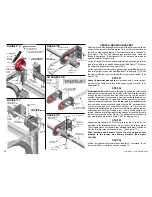
PULL DOWN ROPE & OPTIONAL LIFT HANDLES
About 12“ (305) above the center of the door, fasten the rope strap
to the side of the reverse angle. Fasten the end of the pull down
rope to the rope strap. (See Figure 14C) Fasten the other end of
the pull down rope to the bottom roller bracket. (See Figure 14D)
WARNING! To help protect children, do not fasten pull down rope
to an electrically operated door.
1/4“ X 1” THREAD
FORMING SCREWS
FIGURE 14B
HORIZONTAL
TRACK ANGLE
5/16“X2”
LAG SCREW
3/8“X1”
SHORT NECK
CARRIAGE
BOLT
3/8“ LOCK
NUT
TOP ROLLER BRACKET
RIGHT LOCK-ON
SIDE BEARING BRACKET
FIGURE 14C
FIGURE 14D
#2 DOOR
SECTION
1/4"X1” THREAD
FORMING SCREW
1/4"X1” THREAD
FORMING SCREW
1/4"X1/2" SHORT
NECK CARRIAGE
BOLT AND 1/4"
LOCK NUT
PULL DOWN
ROPE
BOTTOM ROLLER
WITH ROLLER SHIELD
PULL DOWN ROPE
LIFT HANDLE
ROPE STRAP
LIFT HANDLE
BOTTOM
ROLLER
BRACKET
CENTER
LINE
NOTE: For commercial narrow steel jamb
installation, fasten a 4” (102) length of
punched angle to the front of each Lock-On
Side Bearing Bracket. Fasten the punched
angles to the side of each steel jamb.
3/8“ LOCK NUT
Optional insulated
doors are furnished
with 2 inside lift
handles.
COPYRIGHT © 2004 MARTIN DOOR
FIGURE 14A
1/4“ X 1/2” SHORT NECK
CARRIAGE BOLTS AND
1/4“LOCK NUTS
END STILE
SPLICE
PLATE OR
SPLICE
BRACEKT
TOP ROLLER
BRACKET
ROLLER SHAFT
IN ROLLER TUBE
TOP DOOR
SECTION
VERTICAL TRACK
TOP ROLLER WITH
ROLLER SHIELD
HORIZONTAL
TRACK CURVE
3/8“ LOCK
NUTS
1/4“X 1” THREAD
FORMING SCREW
(THREE)
5/16“X2”
LAG SCREWS
3/8“X1” SHORT NECK
CARRIAGE BOLTS
“L” STRUT
LEFT LOCK-ON SIDE BEARING BRACKET
NOTE:
MAKE SURE LOCK-ON SIDE
BEARING BRACKETS ARE
FASTENED VERTICAL (PLUMB)
AND SOLID TO JAMBS
WIDE WOOD DOORS
HAVE 3”(76)“U” STRUTS


