SECTION 7 Technical Information
0855904enb 4/05
m
®
7–19
3.3
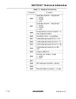
X12 External I/O
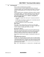
This is a 25-pin miniature D-type connector.
The X12 connector is used for additional machine control and
monitoring signals, such as fault and warning signals, which can be
used for controlling beacons or for linking to the conveyor control
system.
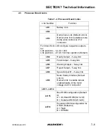
Machine outputs can be configured to operate as volt-free contacts
or as 24VDC outputs. The mode of operation for each output may
be configured individually. A link on the mother board is used to
select the operating mode
(
refer to
Section 7, paragraph 2.3
Processor Board Links)
.
•
The volt-free outputs can source up to 1 amp at a maximum of
30 VDC
•
In 24V mode, the Cimjet can supply up to 1 amp total across all
the outputs using the 24V supply
A number of additional connections are provided:
Motor Safety
When LK9, on the mother board, is removed, the motor safety
connections on X12 must be connected. The relay or output used
must be capable of dealing with 35VDC at 3 amps.
Dump Valve Interlock
When LK3 on the processor board is removed, this allows the two
dump valve interlock connections on X12 to be used to control the
dump valve output. Dump valves are only used on applicators
requiring a hard-wired dump valve to make the machine safe.
The external contact must be capable of handling 0.25 amps at 24
VDC.
Safety Module Connections
The 24V, 0V, E-stop and guard connections allow an optional safety
module to be provided for applicators where the level of risk requires
a hard-wired safety circuit. The N/O or N/C state indicates the state
of the circuit when the Cimjet RFID is powered up and operating in a
fault/warning free condition.
Note:
N/O = Normally Open, C = Common, N/C = Normally Closed
Содержание Cimjet RFID
Страница 1: ...Cimjet RFID Operation Service Manual m Operation Service Manual Cimjet RFID...
Страница 2: ......
Страница 4: ......
Страница 6: ......
Страница 11: ...Cimjet RFID Operation Service Manual m SECTION 1 General Information...
Страница 12: ......
Страница 37: ...SECTION 1 General Information 0855904enb 4 05 m 1 25 Figure 1 1 Cimjet RFID Dispenser left hand option shown...
Страница 39: ...SECTION 1 General Information 0855904enb 4 05 m 1 27 Figure 1 2 Cimjet RFID Front Figure 1 3 Cimjet RFID Rear...
Страница 40: ...SECTION 1 General Information 1 28 m 0855804enb 4 05 Figure 1 4 Cimjet RFID Tag Optic...
Страница 43: ...SECTION 1 General Information 0855904enb 4 05 m 1 31 Figure 1 6 Cimjet RFID Dispenser Stand...
Страница 44: ...SECTION 1 General Information 1 32 m 0855804enb 4 05...
Страница 45: ...Cimjet RFID Operation Service Manual m SECTION 2 Installation Guide...
Страница 46: ......
Страница 51: ...Cimjet RFID Operation Service Manual m SECTION 3 Operating Guide...
Страница 52: ......
Страница 54: ...SECTION 3 Operating Guide 3 2 m 0855904enb 4 05 Figure 3 1 Webbing Diagram left hand option shown...
Страница 65: ...Cimjet RFID Operation Service Manual m SECTION 4 Restricted Access Mode User Guide...
Страница 66: ......
Страница 85: ...Cimjet RFID Operation Service Manual m SECTION 5 Operating Modes...
Страница 86: ......
Страница 93: ...Cimjet RFID Operation Service Manual m SECTION 6 Preventive Maintenance Guide...
Страница 94: ......
Страница 107: ...Cimjet RFID Operation Service Manual m SECTION 7 Technical Information...
Страница 108: ......
Страница 140: ...SECTION 7 Technical Information 7 32 m 0855904enb 4 05...
Страница 141: ...Cimjet RFID Operation Service Manual m SECTION 8 Troubleshooting Guide...
Страница 142: ......
Страница 153: ...Cimjet RFID Operation Service Manual m SECTION 9 Recommended Spares...
Страница 154: ......
Страница 157: ...Cimjet RFID Operation Service Manual m Section 10 Parts Illustrations and Electrical Schematics...
Страница 158: ......


