background image

1 - OPERATING AND SAFETY INSTRUCTIONS

2 - DESCRIPTION

3 - MAINTENANCE

4 - OPTIONAL ATTACHMENTS FOR USE WITH THE RANGE

MT 835 ST3B

MT 1135 ST3B

MT 1335 ST3B

647104 

(13/06/2016) 

MT 

835 

/ 1135 

/ 1335  

ST3B

Содержание MT 1135 ST3B

Страница 1: ...ics given at the time of its design The level of equipment of the lift truck depends on the options chosen and the country of sale According to the lift truck options and the date of sale certain item...

Страница 2: ...t organization that are found in this document are the intellectual property of MANITOU BF Any violation of the aforementioned may lead to civil and criminal prosecution The logos as well as the visua...

Страница 3: ...1 OPERATING AND SAFETY INSTRUCTIONS 2 DESCRIPTION 3 MAINTENANCE 4 OPTIONAL ATTACHMENTS FOR USE WITH THE RANGE MT835ST3B MT1135ST3B MT1335ST3B 647104 13 06 2016 MT 835 1135 1335 ST3B...

Страница 4: ...1 1 1 OPERATING AND SAFETY INSTRUCTIONS 647104 13 06 2016 MT 835 1135 1335 ST3B...

Страница 5: ...1 2 647104 13 06 2016 MT 835 1135 1335 ST3B...

Страница 6: ...1 3 647104 13 06 2016 MT 835 1135 1335 ST3B...

Страница 7: ...BILITY 10 E STARTING THE LIFT TRUCK 11 F DRIVING THE LIFT TRUCK 11 G STOPPING THE LIFT TRUCK 12 H DRIVING THE LIFT TRUCK ON THE PUBLIC HIGHWAY 13 INSTRUCTIONS FOR HANDLING A LOAD 14 A CHOICE OF ATTACH...

Страница 8: ...ING THE LIFT TRUCK 25 TRANSPORTING THE LIFT TRUCK 25 IFTHELIFTTRUCKISNOTTOBEUSEDFORALONGTIME 26 INTRODUCTION 26 PREPARING THE LIFT TRUCK 26 PROTECTING THE ENGINE 26 PROTECTING THE LIFT TRUCK 26 BRINGI...

Страница 9: ...everse lights reverse buzzer alarm front light rear light light at the jib head etc according to the lift truck model The operator must take into account the operating conditions to define the lift tr...

Страница 10: ...melimitdefinedbytheregulations TheoperatormustholdanHGVlicence unlessgrantedanexemption The lift truck must be driven on the public highway in accordance with the instructions given in the manual supp...

Страница 11: ...he establishment with respect to the use of lift trucks and must be carried permanently by the operator The operator is not competent to authorise the driving of the lift truck by another person C MAI...

Страница 12: ...gainst excessive noise Always face the lift truck when getting into and leaving the driving seat and use the handle s provided for this purpose Do not jump out of the seat to get down Always pay atten...

Страница 13: ...ft truck and the aerial line IMPORTANT Youmustconsultyourlocalelectricalagency Youcouldbeelectrocutedorseriouslyinjuredifyouoperateorparkthelifttrucktooclosetopowercables Intheeventofhighwinds donotca...

Страница 14: ...s not show the correct display stop the engine and immediately carry out the necessary operations F DRIVING THE LIFT TRUCK SAFETY INSTRUCTIONS IMPORTANT Theoperators attentionisdrawntotherisksinvolved...

Страница 15: ...easedifthelifttruckisladenortowingatrailer requiringextremevigilance G STOPPING THE LIFT TRUCK SAFETY INSTRUCTIONS Never leave the ignition key in the lift truck during the operator s absence When the...

Страница 16: ...RIPTION INSTRUMENTS AND CONTROLS Fully retract the boom and set the attachment approximately 300 mm off the ground Place the roll corrector in the central position i e the transverse axis of the axles...

Страница 17: ...re of gravity contact your dealer For irregular loads determine the transverse centre of gravity before any movement fig B2 and set it in the longitudinal axis of the lift truck IMPORTANT Itisforbidde...

Страница 18: ...ION INSTRUMENTS AND CONTROLS In this position the two front wheels must be off the ground E TAKING UP A LOAD ON THE GROUND Approach the lift truck perpendicular to the load with the jib retracted and...

Страница 19: ...will go by alternately extending and lowering the jib 1 or if necessary moving the lift truck forward 2 fig F2 Apply the handbrake and place the forward reverse selector in neutral Slightly raise the...

Страница 20: ...RNING DEVICE If necessary move the lift truck 3 forward fig F7 driving very slowly and carefully Place the load in a horizontal position and lay it down on the pile by lowering and retracting the jib...

Страница 21: ...RTANT Thisoperationmustbeexceptionalandperformedwithgreatcare Raise the jib and retract the telescopes completely Set the lift truck in position in front of the elevation fig G2 moving very slowly and...

Страница 22: ...ed set the load back down in the place from which it was taken If possible lower the load without moving the lift truck Raise the jib 1 to release the load retract 2 and lower the jib 3 to set the loa...

Страница 23: ...tly and smoothly to minimise swinging of the load Carry the load a few centimetres above the ground max 30 cm the shortest possible jib length Do not exceed the offset indicated on the load chart If t...

Страница 24: ...int themselves with the emplacement and operation of all control instruments prior to operating the platform Check before use that the platform has been correctly assembled and locked onto the lift tr...

Страница 25: ...t Largerwavesforming whitecapseverywhere somespray 7 Neargale 28 33 50 61 13 9 17 1 Whole trees in motion inconvenience felt whenwalkingagainstthewind Sea heaps up white foam from breaking waves begin...

Страница 26: ...sible place The user must ensure that the instruction manual is accessible at all times and that operators have read and understood it INSTRUCTIONS Take up position in a stable place with no risk of s...

Страница 27: ...ce the safety wedge 1 on the rod of the lifting cylinder and secure with the rod 2 and the pin 3 Slowly lower the jib then stop the hydraulic movements before it comes into contact with the wedge REMO...

Страница 28: ...efore working on the electrical circuit WELDING Disconnect the battery before any welding operations on the lift truck When carrying out electric welding work on the lift truck connect the negative ca...

Страница 29: ...e cold after charging it to a maximum Block the outlet with waterproof adhesive tape Remove the drive belts and store them in a safe place Disconnect the engine cut off solenoid on the injection pump...

Страница 30: ...e granules GLASS Glass items can be removed and collected for processing by glaziers ENVIRONMENTALPROTECTION By entrusting the maintenance of your lift truck to the MANITOU network the risk of polluti...

Страница 31: ...1 28 647104 13 06 2016 MT 835 1135 1335 ST3B...

Страница 32: ...2 1 2 DESCRIPTION 647104 13 06 2016 MT 835 1135 1335 ST3B...

Страница 33: ...2 2 647104 13 06 2016 MT 835 1135 1335 ST3B...

Страница 34: ...RISTICS MT1135ST3B 14 CHARACTERISTICS MT1335ST3B 16 TIRES 18 DIMENSIONSANDLOADCHART MT835ST3B 20 DIMENSIONSANDLOADCHART MT1135ST3B 22 DIMENSIONSANDLOADCHART MT1335ST3B 24 VISIBILITYMT835ST3B 26 VISIBI...

Страница 35: ...clare que cette machine Declares that this machine 7 Est conforme aux directives suivantes et leurs transpositions en droit national Complies with the following directives and their transpositions in...

Страница 36: ...tojas 6 Parei kia kad is renginys 7 Atitinka toliau nurodytas direktyvas ir nacionalinius teis s aktus perkeltas j nuostatas 8 IV priedas d l ma in 9 Sertifikato Nr 10 Paskelbtoji staiga 15 suderintus...

Страница 37: ...izercrushingriskMT1135ST3B MT1335ST3B 4 24653 Slingingpoint 5 305405 Dieselfuel 6 296733 Batterycut offinstruction 7 52551668 Airconditioning option 8 288430 Repairinstruction 9 264476 Electricaljibpr...

Страница 38: ...NDPLATESUNDERTHEENGINEHOOD REF PARTNUMBER DESCRIPTION 1 259398 Water dieselseparator 2 52501046 Anti freeze 3 306583 Enginefuse 4 296741 Donotmount safetyinstruction 3 2 1 4 647104 13 06 2016 MT 835 1...

Страница 39: ...brication Year of manufacture Anno di fabbricazione A o de fabricaci n N de s rie Serial Nr N di serie N de serie Masse vide Unladen mass Massa a vuoto Masa en vacio P T R A Authorized gross vehicle w...

Страница 40: ...11 12 14 0m 1 2 3 5 6 7 8 1 12 30 7 30 2 55 3 05 1 85 2 25 3 65 4 25 5 10 5 60 6 35 8 25 8 75 30 00 KG 300KG 400KG 600KG 1000KG 1200KG 1600KG 2000KG 2500KG 800KG 35 00 KG E D C B A 19 16 N 310977 SUI...

Страница 41: ...l Nr MANITOU reference MANITOU BF 44158 ANCENIS CEDEX FRANCE N 295449 MODELE MODEL MODELLO MODELO SERIE SERIES Ann e de fabrication Year of manufacture Anno di fabbricazione A o de fabricaci n N de s...

Страница 42: ...ATTACHMENT Model Serial Nr Year of manufacture N 207701 MODELE N dans la s rie Ann e fabrication Masse vide C d G Tablier Cap Nominale Pression de service AVERTISSEMENT RESPECTEZ LA CAPACITE DE L ENSE...

Страница 43: ...80 24156A8POWERCL Pressure bar 4 ELECTRIC CIRCUIT Battery STANDARD 12V 110Ah 900AEN OPTION 12V 180Ah 1200AEN Alternator 12V 100A Type ISKRAAAK EF Starter 12V 3 2kW Type ISKRAAZE BRAKE CIRCUIT Service...

Страница 44: ...tilting unladen s s 3 42 1 SPECIFICATIONS AND WEIGHTS Speed of movement for lift truck in standard configuration on flat ground exceptparticularconditions Front unladen 1 km h 5 1 2 km h 8 1 3 km h 15...

Страница 45: ...80 24156A8POWERCL Pressure bar 4 ELECTRIC CIRCUIT Battery STANDARD 12V 110Ah 900AEN OPTION 12V 180Ah 1200AEN Alternator 12V 100A Type ISKRAAAK EF Starter 12V 3 2kW Type ISKRAAZE BRAKE CIRCUIT Service...

Страница 46: ...ck in standard configuration on flat ground exceptparticularconditions Front unladen 1 km h 5 1 2 km h 8 1 3 km h 15 2 4 km h 25 7 Rear unladen 1 km h 5 1 2 km h 8 1 3 km h 15 2 4 km h 25 7 Standard a...

Страница 47: ...80 24156A8POWERCL Pressure bar 4 ELECTRIC CIRCUIT Battery STANDARD 12V 110Ah 900AEN OPTION 12V 180Ah 1200AEN Alternator 12V 100A Type ISKRAAAK EF Starter 12V 3 2kW Type ISKRAAZE BRAKE CIRCUIT Service...

Страница 48: ...lift truck in standard configuration on flat ground exceptparticularconditions Front unladen 1 km h 5 1 2 km h 8 1 3 km h 15 2 4 km h 25 7 Rear unladen 1 km h 5 1 2 km h 8 1 3 km h 15 2 4 km h 25 7 St...

Страница 49: ...LLIANCE 400 80 R24A325162A8 4 PRESSURE bar LOAD kg PRESSUREONTHECONTACTSURFACE kg cm2 AREAOFTHECONTACTSURFACE cm2 HARDSOIL LOOSESOIL HARDSOIL LOOSESOIL MICHELIN 460 70 R24XMCL159A8 4 600 6 67 2 55 90...

Страница 50: ...2 19 647104 13 06 2016 MT 835 1135 1335 ST3B...

Страница 51: ...mm 5120 D2 mm 4203 E mm 6548 F mm 1846 F1 mm 1846 G mm 445 G1 mm 415 G2 mm 445 I mm 865 J mm 884 K mm 1040 L mm 45 N mm 1740 1803 O mm 125 P2 38 P3 44 R mm 3460 S mm 7910 T mm 3745 U1 mm 2419 U2 mm 25...

Страница 52: ...ME EN 1459 annexe B 50 60 68 D C B A 8 7 6 5 4 3 2 1 0m 40 30 20 10 0 3 7 75 D C B A 0 5m 5 4 3 2 1 0m 3500KG 3000KG 2500KG 2000KG 1500KG 1200KG 1150KG 4 25 1 50 2 95 1 95 4 45 3 70 2 45 1 70 647104 1...

Страница 53: ...35ST3B A mm B mm C mm C1 mm D mm D1 mm D2 mm E mm F mm F1 mm G mm G1 mm G2 mm G3 mm H H1 I mm J mm K mm L mm N mm O mm P2 P3 R mm S mm T mm U1 mm U2 mm V mm V1 mm V2 mm W mm W1 mm W2 mm W3 mm Y Z 6471...

Страница 54: ...50 5 65 4 85 4 25 3 75 50 1 10 20 30 40 60 72 11 05 MT 1135 MT 1135 H MT 1135 HA N 310973 SUIVANT NORME EN 1459 annexe B MT1135 68 60 50 40 30 20 10 0 3 10 75 10 8 7 6 5 4 3 2 0 1 2 3 4 5 6 7 8 9 0m 1...

Страница 55: ...6 F mm 1870 F1 mm 1870 G mm 445 G1 mm 415 G2 mm 445 G3 mm 135 H 10 H1 10 I mm 1178 J mm 884 K mm 1040 L mm 45 N mm 1740 1803 O mm 125 P2 38 P3 31 R mm 3643 S mm 8097 T mm 4084 U1 mm 2419 U2 mm 2559 V...

Страница 56: ...8 25 8 75 3000KG 300KG 400KG 600KG 1000KG 1200KG 1600KG 2000KG 2500KG 800KG 3500KG E D C B A MT 1335 MT 1335 H MT 1335 HA N 301819 SUIVANT NORME EN 1459 annexe B 4 55 5 85 8 05 1 80 5 20 6 75 8 75 30...

Страница 57: ...DEN D VISIBILITY DESCRIPTIONANDADJUSTMENTOFREAR VIEWMIRRORS 1 LEFT REAR VIEW MIRROR 2 MAIN RIGHT REAR VIEW MIRROR 3 CENTRAL RIGHT REAR VIEW MIRROR 4 UPPER RIGHT REAR VIEW MIRROR 5 REAR REAR VIEW MIRRO...

Страница 58: ...000 50 r 12 m 9 5 m 45 45 A F E D B C DIRECTAND ORINDIRECTVISIBILITYBLINDSPOTZONES In accordance with EN15830 the two diagrams indicate blind spot zones on the visibility test circle r 12m and the 1m...

Страница 59: ...ADEN D VISIBILITY DESCRIPTIONANDADJUSTMENTOFREAR VIEWMIRRORS 1 LEFT REAR VIEW MIRROR 2 MAIN RIGHT REAR VIEW MIRROR 3 CENTRAL RIGHT REAR VIEW MIRROR 4 UPPER RIGHT REAR VIEW MIRROR 5 REAR REAR VIEW MIRR...

Страница 60: ...000 50 r 12 m 9 5 m 45 45 A F E D B C DIRECTAND ORINDIRECTVISIBILITYBLINDSPOTZONES In accordance with EN15830 the two diagrams indicate blind spot zones on the visibility test circle r 12m and the 1m...

Страница 61: ...ADEN D VISIBILITY DESCRIPTIONANDADJUSTMENTOFREAR VIEWMIRRORS 1 LEFT REAR VIEW MIRROR 2 MAIN RIGHT REAR VIEW MIRROR 3 CENTRAL RIGHT REAR VIEW MIRROR 4 UPPER RIGHT REAR VIEW MIRROR 5 REAR REAR VIEW MIRR...

Страница 62: ...the two diagrams indicate blind spot zones on the visibility test circle r 12m and the 1m rectangular zone around the lift truck LOADING THE TRAILER r 12 m 9 5 m 45 45 A F E D B C 1000 50 r 12 m 9 5 m...

Страница 63: ...15 21 36 20 12 8 9 11 41 5 1 4 16 6 7 30 14 16 16 16 19 17 18 20 36 24 23 24 2 25 22 25 25 24 27 28 34 29 13 24 3 MT1135ST3B MT1335ST3B 4 16 19 20 MT835ST3B 8 31 INSTRUMENTS AND CONTROLS 647104 13 06...

Страница 64: ...LEVER 21 STEERING SELECTION 22 HEATER CONTROL 23 AIR CONDITIONING CONTROLS AIR CONDITIONING OPTION 24 HEATING VENTS 25 DEMIST VENTS 26 LEVEL INDICATORS 27 DOOR OPEN LEVER 28 DOOR CLOSE HANDLE 29 WINDO...

Страница 65: ...n can be adjusted separately To adjust the front push the lever 2 downwards Release it into one of the five possible positions Same procedure to adjust the back by pulling the lever 2 upwards SEAT SUS...

Страница 66: ...n the handle either left or right to adjust the height or depth of the lumbar support ADJUSTMENT OF THE ANGLE OF THE BACK REST FIG G IMPORTANT Ifyoudonotsupporttheback restwhenmakingadjustments itswin...

Страница 67: ...LE ADJUSTMENT FIG C The back rest angle of the seat may be adjusted to suit the individual Press the left hand button while pushing on the seat or relaxing pressure on the seat to find a comfortable p...

Страница 68: ...To clean or change the cushions simply remove them from the seat frame Avoid wetting the cushion fabric when cleaning Check the resistance of the fabric on a small hidden area before using any fabric...

Страница 69: ...rom the Man Machine Interface of your lift truck contact your dealer to receive the most recent available version of the software 6A 6D 6B 6C 5 BATTERYCUTOFF For quickly disconnecting the battery when...

Страница 70: ...codes see 2 DESCRIPTION 6D SCREEN DISPLAY MENU SCREEN GREEN LIGHT FOR LOW BEAM BLUE LIGHT FOR MAIN BEAM AIR FILTER CLOGGING LAMP The lamp comes on when the air filter cartridge is clogged up When this...

Страница 71: ...immediately and check the electric circuit and the alternator belt GREEN PROGRESSIVE INCHING TRANSMISSION MODE INDICATOR LAMP OPTION This lamp comes on when using the progressive transmission INCHING...

Страница 72: ...default mode OPTION PROGRESSIVE TRANSMISSION INCHING MODE IN FORWARD AND REVERSE GEAR OPTION The indicator on the instrument control panel will light when it is in use The operating screen displays t...

Страница 73: ...tabilisers the display in zone 2 on the operating screen switches to zone 7 CHANGEMODE ONTYRES Press 1 2 1 2 Confirm Cancel ONTYRES Press 1 2 1 2 Confirm Cancel ONTYRES Press 1 2 1 2 Confirm Cancel AD...

Страница 74: ...is advised to disable the revolving light when the ignition is switched off to avoid a flat battery MENU SCREEN DISPLAY A flashing lamp indicates a fault see 2 DESCRIPTION 6D SCREEN DISPLAY MENU SCRE...

Страница 75: ...is screen appears If the screen remains permanently displayed contact your dealer DIGIC 0 0 _ _ DIGICODE SCREEN The digicode is disabled by default It can be enabled from the OPT menu on the menu scre...

Страница 76: ...stparticlefilterregenerationdisabled see 8 SWITCHES Highorveryhighsootlevel see 8 SWITCHES 7 Blankscreen Transmissionlockedinneutral driverpresencenotvalidated OPTIONProgressiveINCHINGtransmissionmode...

Страница 77: ...atic regenerationenabledmode see 2 DESCRIPTION 8 SWITCHES Moderatesootlevelinexhaustparticlefilterautomatic regenerationdisabledmode see 2 DESCRIPTION 8 SWITCHES Stationarylifttruck exhaustparticlefil...

Страница 78: ...or not permitted UNIT Speed of travel displayed in MPH or Km h by default DIGI1 Digicode enabled by default or not enabled DIGI2 Change the 4 figure digicode lift truck start up CUST Change the custom...

Страница 79: ...in the transport position Hold down the button the SUSPENDED LOAD MODE is confirmed by a beep and the lighting of the indicator lamp Hydraulic inclination movements are neutralised as well as the lift...

Страница 80: ...ffunctionis disconnected C1 BUCKET MODE A6 Abeepuponpassingintothe redzone A6 Abeepuponpassingintothe redzone WhenindicatorlampC1islit the AGGRAVATING hydraulic movementcut offfunctionis disconnected...

Страница 81: ...2 50 F STRAIN GAUGE IMPORTANT Disassemblyorcalibrationofthestraingageisprohibited thismustonlybedonebyspeciallytrainedpersonnel consultyourdealer F 647104 13 06 2016 MT 835 1135 1335 ST3B...

Страница 82: ...neutralised as well as the lifting movement when the longitudinal limit is reached indicator lamp A8 lit Press this button again or switch off the ignition with the ignition key to return to HANDLING...

Страница 83: ...s disconnected C1 SUSPENDEDLOAD MODE A4 A5 Veryslowintermittentsoundalarm A6 Slowintermittentsoundalarm A7 Fastintermittentsoundalarm A8 Veryfastintermittentsoundalarm D DISABLING AGGRAVATING HYDRAULI...

Страница 84: ...of the screen and an audible beep followed by the screen on the operating display confirm that it has been disabled To re enable automatic regeneration of the exhaust particle filter hold down the bo...

Страница 85: ...ng 15A F19 OPTION Roof windscreen wiper and windscreen washer 7 5A F20 Window winder 20A F21 Roof light door switch driver seat switch 3A F22 Man Machine Interface MMI 3A F23 OPTION 2A F24 Front winds...

Страница 86: ...d for front windscreen wiper C Fast speed for front windscreen wiper D Front windscreen wiper intermittent control E Front windscreen washer pulse driven REAR WINDSCREEN WIPER F Rear windscreen wiper...

Страница 87: ...ntofsuspectedmalfunction contactyourdealer ANYALTERATIONMAYRENDERTHEWARRANTYNULL ANDVOID Usethehydrauliccontrolscarefullywithoutjerking toavoidaccidentscausedbyshakingthelifttruck MT835ST3B A Lifting...

Страница 88: ...tract fully L H STABILISER Move lever C forwards to lower Move lever C backwards to lift R H STABILISER Move lever D forwards for lowering Move lever D backwards for lifting NOTE Thestabiliserscanonly...

Страница 89: ...nd go up to 4th if the conditions and state of the road permit it In hilly areas set off in 2nd gear and go up to 3rd if the conditions and state of the road permit it With a trailer on the road Set o...

Страница 90: ...lsandtodriveinfrontwheelsteer Thecontrolofthealignmentoftherearwheelsmustberegularlydonewiththehelpofthegreenlamps whiledrivingthelifttruck Incaseofanomalies consultyourdealer Shift the steering selec...

Страница 91: ...ure inside the cab to be adjusted B1 The fan pumps in cold air B2 The fan pumps in warm air The intermediate positions allow the temperature to be adjusted C AIR CONDITIONING CONTROL This control with...

Страница 92: ...LT INDICATOR MT1135ST3B MT1335ST3B When the two marks are aligned the chassis is parallel with the front axle B SPIRIT LEVEL Enables the operator to check that the lift truck is in the horizontal posi...

Страница 93: ...36 DOCUMENTHOLDERNET Make sure that the operator s manual is in the right place i e in the document holder net NOTE An OPTION waterproof document holder exists 37 ASHTRAY 38 FRONTHEADLIGHTS A Left fr...

Страница 94: ...o socket 1 41 INSIDEREAR VIEWMIRROR 42 BOOMSAFETYWEDGE IMPORTANT Onlyusethewedgesuppliedwiththelifttruck The lift truck is equipped with a boom safety wedge that must be installed on the rod of the li...

Страница 95: ...gerscaughtorcrushedduringthisoperation Donotforgettoputpinbackinplace Whenuncoupling makesurethatthetrailerissupportedindependently COUPLING AND UNCOUPLING THE TRAILER To couple the trailer position t...

Страница 96: ...2 65 647104 13 06 2016 MT 835 1135 1335 ST3B...

Страница 97: ...ECT REAR HYDRAULIC CONTROL PREDISPOSITION 12 LIFTING RING ON SINGLE CARRIAGE 1 LICENSEPLATELIGHT 2 MODCLEANTI STARTSYSTEM OPERATION Switch on lift truck ignition red led 1 will flash Apply key 2 to it...

Страница 98: ...on drain back connected 5 ANGULARSECTORONBOOM The angular sector displays the boom angle and thus improves the reading of the load charts 3 BOOMELECTRICALPREDISPOSITION Enables an electrical function...

Страница 99: ...d ATTACHMENT LINE L2 CONTROL Hold down button 2 and push button 1 forwards or backwards 9 TELESCOPEHEADELECTROVALVE HYDRAULICATTACHMENTLOCKING The addition of these two options on the attachment line...

Страница 100: ...ght and backward to move sideways to the left WITHTELESCOPEHEADELECTROVALVE TSDL LINE L1 CONTROL Push button 2 forward to move sideways to the right and backward to move sideways to the left ATTACHMEN...

Страница 101: ...NHANDLINGLOADS inadditiontothosegivenbelow The lifting ring must be used WITHOUT FORKS AND ATTACHMENTS but the angle of inclination of the carriage must be same as when the forks are used in the horiz...

Страница 102: ...45 Maxi 1 5km h Maxi 0 4m s N 319881 N 319881 MT1335 TS AS MT1335 TS AS 3m Mini 1 55m Maxi 0 3m Maxi 8 84m 7 92 6 3 4 85 4 3 3 8 3 35 2 85 2 3 1 45 0m 1 2 4 3 5 6 7 8 0 1 2 3 4 5 6 7 8 9 1 A B C D E...

Страница 103: ...2 72 647104 13 06 2016 MT 835 1135 1335 ST3B...

Страница 104: ...3 1 3 MAINTENANCE 647104 13 06 2016 MT 835 1135 1335 ST3B...

Страница 105: ...3 2 647104 13 06 2016 MT 835 1135 1335 ST3B...

Страница 106: ...RVICINGSCHEDULE 8 A DAILYOREVERY10HOURSSERVICE 10 B EVERY50HOURSSERVICE 14 C EVERY250HOURSOFSERVICE 20 D EVERY500HOURSOFSERVICEOREVERYYEAR 22 E EVERY1000HOURSOFSERVICEOREVERYTWOYEARS 26 F EVERY2000HOU...

Страница 107: ...FORMAINTENANCEOPERATIONS YOUBENEFITFROMOURKNOW HOW Through its network MANITOU provides the user with Know how and competence The guarantee of high quality work Original replacement parts Help with pr...

Страница 108: ...798466 Change 500 H COMPRESSOR BELT OPTION AIR CONDITIONING Part number 216125 TRANSMISSION GEAR BOX OIL FILTER Part number 745878 Change 1000 H HYDRAULIC HYDRAULIC RETURN OIL FILTER CARTRIDGE Part nu...

Страница 109: ...PICJ4 15W40 40 C 30 20 10 0 10 20 30 40 50 C COOLING CIRCUIT 17Liters COOLINGLIQUID 35 C 40 C 30 20 10 0 10 20 30 40 50 C FUEL TANK 120Liters GNRHPDIESEL TRANSMISSION PARTSTOBELUBRICATED CAPACITY RECO...

Страница 110: ...LUEMULTI USELUBRICANT ATTACHMENT PARTSTOBELUBRICATED RECOMMENDATION 40 C 30 20 10 0 10 20 30 40 50 C SINGLE SIDE SHIFT CARRIAGE TSDL OPTION MANITOUBLUEMULTI USELUBRICANT PACKAGING OIL PRODUCT PACKAGIN...

Страница 111: ...nkcaseventilationfilter 3 26 R Fueltank 3 27 N Enginesilentblocks C 3 Enginerates C 3 Valvesclearances C C 3 Coolingliquid 3 30 V Radiator C 3 Waterpumpandthethermostat C 3 Alternatorandthestartermoto...

Страница 112: ...Frontwheelreductiongearpivots 3 18 19 G G G C 3 FrontaxleoscillationMT1135ST3B MT1335ST3B 3 18 19 G G G C 3 Frontaxledifferentialoillevel 3 21 C Frontwheelsreductiongearoillevel 3 21 C Frontaxlediffe...

Страница 113: ...uchacase thecoolingsystemfluidshouldbechangedsoon aspossible see3 MAINTENANCE F1 COOLINGLIQUID Open the engine bonnet The liquid must be at the MAXIMUM level on the expansion tank 1 If necessary add c...

Страница 114: ...water Retighten drain plug 2 and bleed screw 3 A5 BOOMPADS CLEAN GREASE To be carried out every 10 hours during the first 50 hours service then once at 250 hours IMPORTANT Ifthelifttruckisusedinanabr...

Страница 115: ...t h e n p r e s s Raisetheboomandretractthetelescopescompletely Validate TEST R e t r a c t Te l e s c o p e O K B o o m S e n s o r N O K S t r a i n G a u g e N O K TESTOK Gotostage4 TESTNONOK Valid...

Страница 116: ...3 13 647104 13 06 2016 MT 835 1135 1335 ST3B...

Страница 117: ...cooling air flow 4 1 2 3 B2 GEARBOXOILLEVEL CHECK Place the lift truck on level ground with the boom raised and the engine running IMPORTANT Raisetheboomandplacetheboomsafetywedgeontherodofthelifting...

Страница 118: ...repressuresgiven Check the condition of the tyres to detect cuts protuberances wear etc Check the torque load of the wheel nuts Non compliance with this instruction can cause damage and rupture to the...

Страница 119: ...cator 7 Lubricator of the compensation cylinder foot axle 1 lubricator 8 Lubricator of the compensation cylinder head axle 1 lubricator FRONT AND REAR WHEEL REDUCTION GEAR PIVOTS 9 Lubricators of the...

Страница 120: ...3 17 17 17 17 17 17 17 17 17 1 1 9 9 8 6 3 4 2 2 14 16 16 14 10 10 16 15 11 11 12 13 12 9 9 7 5 647104 13 06 2016 MT 835 1135 1335 ST3B...

Страница 121: ...p lock 2 Remove cap 3 Add oil through filler port 4 up to the black dot on the high level gauge 5 Refit the cap and its lock Visually check that there is no leakage in the tank and pipes B6 BRAKEOILLE...

Страница 122: ...ERNAL CAB VENTILATION FILTER Remove the protective grid 3 Lift out cab ventilation filter 4 Clean the filter with a compressed air jet Check its condition and change if necessary see 3 MAINTENANCE FIL...

Страница 123: ...l pressure exerted with the thumb 45 N the belt should move approximately 10 mm Adjust if necessary Loosen the screws 3 by two to three turns Swivel the compressor assembly so as to obtain the belt te...

Страница 124: ...g 1 tightening torque 34 to 49 N m C4 FRONTANDREARWHEELREDUCTIONGEAROILLEVEL CHECK Place the lift truck on level ground with the engine stopped Check the level on each wheel reduction gear Place level...

Страница 125: ...l and filling plug 4 to ensure that the oil is drained properly REPLACEMENT OF THE FILTER Unscrew and discard the engine oil filter 5 together with its seal Clean the filter bracket with a clean lint...

Страница 126: ...sembly by hand only onto the head of the pre filter until mark A is aligned Replace the fuel filter cartridge D4 FUELFILTERCARTRIDGE CHANGE IMPORTANT Carefullycleantheoutsideofthefilteranditsholder to...

Страница 127: ...level is correct when the oil level is flush with the edge of opening 2 Check for any possible leaks at the drain plugs Refit and tighten level plug 2 tightening torque 34 to 49 N m and filler plug 3...

Страница 128: ...3 25 647104 13 06 2016 MT 835 1135 1335 ST3B...

Страница 129: ...ntheairfilterandtheengineandtheconnection and state of the clogging indicator on the filter Before mounting check the state of the new filter cartridge see 3 MAINTENANCE FILTERS CARTRIDGES AND BELTS T...

Страница 130: ...topped the gear box oil still warm IMPORTANT Raisetheboomandplacetheboomsafetywedgeontherodoftheliftingcylinder see 1 OPERATINGANDSAFETYINSTRUCTIONS LIFTTRUCKMAINTENANCEINSTRUCTIONS Disposeofthedraino...

Страница 131: ...sbeforeanyinterventioninordertopreventanyrisk ofpollutingthehydrauliccircuit Lift out protective casing 1 Unscrew the fastening screws of the cover 2 Wait a few moments while the oil flows into the ta...

Страница 132: ...locking mechanism when the strap is given a sharp tug NOTE After an accident replace the seat belt E8 FRONTANDREARWHEELREDUCTIONGEAROIL DRAIN Place the lift truck on level ground with the engine stopp...

Страница 133: ...r emptying Let the cooling circuit drain entirely while ensuring that the ports do not get clogged Check the condition of the hoses as well as the fastening devices and change the hoses if necessary R...

Страница 134: ...ondition and replace if necessary see 3 MAINTENANCE FILTERS CARTRIDGES AND BELTS Refit the suction strainer making sure the seal is in the correct position REPLACING THE BRAKE ACCUMULATOR UNIT FILTER...

Страница 135: ...OLS Intheeventofinhalation takethevictimintofreshair giveoxygenorartificialrespirationifnecessaryandcalladoctor Intheeventofcontactwiththeskin washitimmediatelyunderrunningwaterandremoveanycontaminate...

Страница 136: ...3 33 647104 13 06 2016 MT 835 1135 1335 ST3B...

Страница 137: ...t be changed once for every three changes of the dry air filter G2 ALTERNATORBELT CHANGE Open engine bonnet and the lower cover Remove the protective casing 1 REMOVING THE BELT Loosen screws 2 by two...

Страница 138: ...3 35 647104 13 06 2016 MT 835 1135 1335 ST3B...
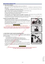
Страница 139: ...oubt contact your dealer H2 STATIONARYLIFTTRUCK EXHAUSTPARTICLEFILTER REGENERATE IMPORTANT Exhaustparticlefiltercleaningisanautomatedprocedureactivatedbytheoperatorwhen help screens or or or aredispla...

Страница 140: ...ingchangedonthepublichighway securethelifttruckvicinity Stop the lift truck if possible on firm level ground Shut down the lift truck see 1 OPERATING AND SAFETY INSTRUCTIONS DRIVING INSTRUCTIONS UNLAD...

Страница 141: ...validate STAGE1 GAUGE F u l l y e x t e n d t h e s t a b i l i z e r s t h e n p r e s s Fully extend the stabilizers MT1135ST3B MT1335ST3B Validate STAGE2 GAUGE R e t r a c t t e l e s c o p e L i f...

Страница 142: ...m in relation to the ground h2 Height of the adjusted beam l Distance between the dipped beam and the white wall H6 BATTERYFAILURE CHANGE IMPORTANT Operatethebatterycut outnolessthan30secondsafterhavi...

Страница 143: ...elease the brake disk Leave a minimum clearance of 5 mm between the disk 4 and the brake pads 5 Put the towing device into place Remove the chocks Switch on the warning lights NOTE Since there will be...

Страница 144: ...oftheturboshaft withoutlubricationwhentransportingthevehicle LOADING THE LIFT TRUCK Block the wheels of the platform Attach the loading ramps to the platform in such a way as to give the shallowest po...

Страница 145: ...3 42 647104 13 06 2016 MT 835 1135 1335 ST3B...

Страница 146: ...4 1 4 OPTIONAL ATTACHMENTS FOR USE WITH THE RANGE 647104 13 06 2016 MT 835 1135 1335 ST3B...
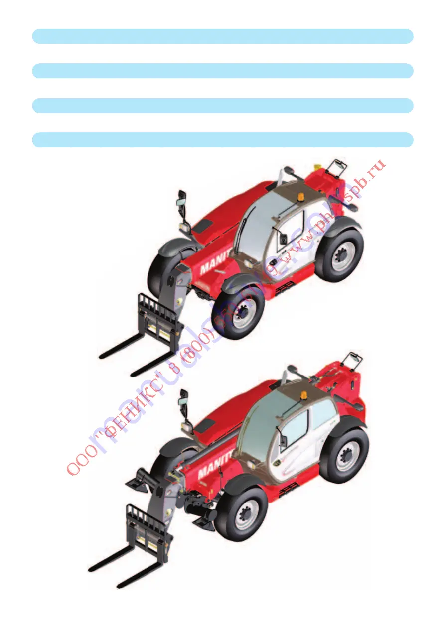
Страница 147: ...4 2 647104 13 06 2016 MT 835 1135 1335 ST3B...

Страница 148: ...TABLE OF CONTENTS 4 OPTIONAL ATTACHMENTS FOR USE WITH THE RANGE INTRODUCTION 5 PICKINGUPTHEATTACHMENTS 6 TECHNICALSPECIFICATIONSOFATTACHMENTS 8 ATTACHMENTSHIELDS 14 647104 13 06 2016 MT 835 1135 1335...

Страница 149: ...4 4 647104 13 06 2016 MT 835 1135 1335 ST3B...

Страница 150: ...SK EXTENDTHETELESCOPETOASUFFICIENTEXTENTFORTHEPARTICULARLIFTTRUCKANDATTACHMENTSOTHATTHISCONTACTISNOTPOSSIBLE SUSPENDED LOAD IMPORTANT SuspendedloadMUSTbehandledwithalifttruckdesignedforthatpurpose see...

Страница 151: ...ge under the locking tube of the attachment slightly lift the boom incline the carriage backwards in order to position the attachment fig C Lift the attachment off the ground to facilitate locking HAN...

Страница 152: ...urethattherapidconnectorsarecleanandprotecttheholeswhicharenotused withthecapsprovided Take the locking pin and the clip on the bracket fig A and lock the attachment fig D Do not forget to refit the c...

Страница 153: ...OATING FORK CARRIAGE TFF35MT 1040 TFF35MT 1300 PARTNUMBER 654093 654094 Rated capacity 3500kg 3500kg Width 1040mm 1300mm Weight 300kg 325kg FLOATING FORK PARTNUMBER 415801 Section 125x45x1200mm Weight...

Страница 154: ...edwiththeoptionalsingleside shiftcarriage TSDL TDL3T5L1260FEM3 TDL5TL1470FEM3 TDL5TL1580FEM3 PARTNUMBER 751375 751376 751377 Rated capacity 3500kg 5000kg 5000kg Side shift 2x100mm 2x100mm 2x100mm Widt...

Страница 155: ...pacity 893l Width 2450mm Weight 410kg LOADING BUCKET CBR1000L2450S2 PARTNUMBER 654716 Rated capacity 990l Width 2450mm Weight 410kg BUCKET 4X1 Useisprohibitedwiththeoptionalsingleside shiftcarriage TS...

Страница 156: ...0mm 1100mm Weight 205kg 220kg CONCRETE BUCKET WITH SPOUT ADAPTABLE ON FORKS BBG500S4 BBHG500S4 PARTNUMBER 654411 751464 Rated capacity 500l 1300kg 500l 1300kg Width 1100mm 1100mm Weight 220kg 235kg CO...

Страница 157: ...CRANE JIB P4000MTS2 PARTNUMBER 653226 Rated capacity 4000kg 1200kg Weight 210kg CRANE JIB PC40 PC50 PARTNUMBER 708553 708544 Rated capacity 4000kg 5000kg Weight 120kg 120kg WINCH H3T PARTNUMBER 885236...

Страница 158: ...4 13 647104 13 06 2016 MT 835 1135 1335 ST3B...

Страница 159: ...thewidthoftheprotectoryouchooseislessthanorequaltothewidthofthebucket PARTNUMBER 206734 206732 206730 Width 1375mm 1500mm 1650mm PARTNUMBER 235854 206728 206726 Width 1850mm 1950mm 2000mm PARTNUMBER 2...

Отзывы:

Похожие инструкции для MT 1135 ST3B