background image

3-28

1.240

1.250

1.260

1.270

1.280

1.290

1.300

°C

°F

18

0

-10

14

0

32

10

50

20

68

30

86

40

104

D10

D10 - 

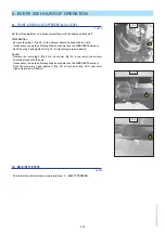
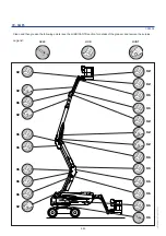
DENSITY OF THE BATTERY ELECTROLYTE 

CHECK

The electrolyte’s density varies according to the temperature but a minimum level 

of 1260 at 16°C must be maintained.

In the hatched section (Fig. D10), the battery is normally charged.
Above the hatched section, the battery must be recharged.

The density must not vary by 0.025 unit from one battery element to another.

- Open the battery cover.

- Check the electrolyte density in each battery element with an acidometer.

- Never check after having added distilled water. Recharge the battery and wait 1 

hour before checking the battery electrolyte’s density.

Manipulating and servicing a battery can be dangerous; take the 
following precautions:
- Wear protective goggles.
- Keep the battery horizontal when manipulating it.
- Never smoke or work close to a naked flame.
- Work in a sufficiently well-ventilated area.
- If some electrolyte splashes onto your skin or in your eyes, rinse 
the affected area thoroughly with cold water for 15 minutes and call 
a doctor.

D11 - 

TIGHTENING THE BOLTS ON THE TURRET ORIENTATION CROWN 

GEAR

CHECK

- The tightness of the screws must be checked at the latest after 50 hours of 

operation. This check must then be repeated every 500 hours of operation.

- The tightening torque for the screws is

 27 daN.m ± 10 %.

- 1 daN = 1 Kg.

D12 - 

BRAKING

CHECK

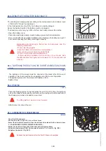
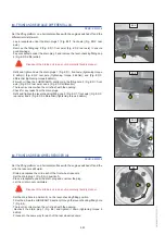
- Check the braking system by disconnecting the coil 1(Fig. D12) from the hydraulic 

unit on the chassis (to access the unit, remove the casing on the left-hand side of 
the chassis) and make a translation movement.

The lifting platform must not move forward.

- After the test, reconnect the coil.

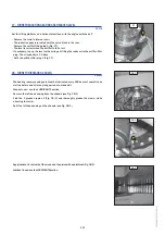
D13 - ALTERNATOR/FAN/CRANKCASE BELT

REPLACE

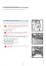
- Open the left-hand cowl.
- Loosen the bolts 1 (Fig. D13)  two or three turns.
- Swivel the alternator assembly to free the belt and the replace it with a new one (see: 

3 - MAINTENANCE: FILTER ELEMENTS AND BELTS).

- Adjust the tension between the crankcase and alternator pulleys.
- Under thumb pressure (98 N), the tension should be 7 to 9 mm (A, Fig. D13)
- Retighten the bolts 1 (Fig. D13).

Recheck the belt tension after the first 20 hours of operation.

D13

1

D13

1

A

1

547408 EN (15/05/2012)

Содержание 160 ATJ PLUS Euro 3

Страница 1: ...Euro 3 180 ATJS Euro 3 MANITOU BF BP 10249 44158 ANCENIS CEDEX FRANCE TEL 33 0 2 40 09 10 11 YOUR DEALER THIS INSTRUCTIONS MANUAL MUST BE KEPT PERMANENTLY IN THE LIFT TRUCK AND THE OPERATORS MUST HAVE...

Страница 2: ...to ensure that the platform remains in a completely safe and operational condition The platform has been designed and produced to enable you to perform your overhead work completely safely Before it w...

Страница 3: ...TRATIONS IN THIS DOCUMENT MAY NOT BE REPRODUCED EITHER IN WHOLE OR IN PART 07 12 2010 21 11 2011 15 05 2012 1st Publication date Update 1 20 1 23 2 10 2 12 2 15 2 18 2 19 2 22 2 23 2 26 2 28 2 34 2 35...

Страница 4: ...180 ATJ Euro 3 160 ATJ PLUS Euro 3 FRONT REAR FRONT REAR 547408 EN 15 05 2012...

Страница 5: ...1 1 1 OPERATING AND SAFETY INSTRUCTIONS 1 OPERATING AND SAFETY INSTRUCTIONS 547408 EN 15 05 2012...

Страница 6: ...1 2 547408 EN 15 05 2012...

Страница 7: ...E 1 15 PLATFORM MAINTENANCE INSTRUCTIONS 1 16 GENERAL INSTRUCTIONS 1 16 MAINTENANCE 1 16 LUBRICANT AND FUEL LEVELS 1 16 LEVEL OF ELECTROLYTE IN THE BATTERY 1 16 HYDRAULIC 1 17 ELECTRICITY 1 17 WELDING...

Страница 8: ...drive a platform operator tempted to operate a truck to win a bet in competition or for their own personal experience The person in charge of the equipment must take these criteria into account when...

Страница 9: ...ur platform hydraulic pressure calibrating limiters I C engine speed addition of extra equipment addition of counterweight unapproved attachments alarm systems etc yourself In this event the manufactu...

Страница 10: ...for it on the platform and be written in the language used by the operator Any operations or manoeuvres not described in the operator s manual must necessarily be forbidden right from the start Follo...

Страница 11: ...eries The batteries are not charged in an explosive environment There is no smoking and no naked flame directed towards the batteries when they are being handled During removal re installation and che...

Страница 12: ...seat extending arms or legs or in general any part of the body outside the basket is forbidden Safety helmets must be worn MANITOU recommends a safety harness in the operator s size be provided when t...

Страница 13: ...cannot slip off and fall Do not heap up these materials to the pint where you have to step over them If the basket must remain stationary over a structure for a long period there is a risk that the ba...

Страница 14: ...retches of water moderate waves of some length 6 Strong breeze 22 27 39 49 10 8 13 8 Large branches are moved overhead wires whistle umbrella use becomes difficult Waves form with white foam crests an...

Страница 15: ...g into a low doorway overhead electric wires travelling cranes highway bridges tracks or any obstacle in the area in front of the platform In reverse look directly behind you In any case avoid reversi...

Страница 16: ...gage the starter motor for more than 15 seconds and carry out the preheating for 10 seconds between unsuccessful attempts Check all control instruments when the I C engine is warm and at regular inter...

Страница 17: ...control of your speed Travel slowly on damp slippery or uneven terrain or on truck ramps Always remember that the hydraulic form of steering is very sensitive to movements Never leave the I C engine o...

Страница 18: ...e platform after a long working period leave the I C engine idling for a few moments to allow the coolant liquid and oil to lower the temperature of the I C engine and transmission Do not forget this...

Страница 19: ...without damaging the electronic components The power supply to the welding equipment must be via an earthed socked and any extension required just also be earthed In all cases ensure that there are n...

Страница 20: ...s Failure to perform the periodic service may cancel the contractual guarantee MAINTENANCE LOG The maintenance work performed following the recommendations in Part 3 MAINTENANCE and the other inspecti...

Страница 21: ...zed personnel WELDING ON THE ACCESS PLATFORM Disconnect the battery or batteries before welding on the platform When carrying out electric welding work on the platform connect the negative cable from...

Страница 22: ...gine running at idling speed for a few minutes then switch off Replace the I C engine oil and oil filter see 3 MAINTENANCE Add the protective product to the engine oil Run the I C engine for a short t...

Страница 23: ...cut off solenoid Refit and reconnect the battery Remove the protection from the cylinder rods Perform the daily service see 3 MAINTENANCE Empty and replace the fuel and replace the fuel filter see 3...

Страница 24: ...598897 598892 A 6 15 15 10 598897 598892 A 230 Kg 70 Kg 510 Lbs 155 Lbs 2 12 5 m s 45km h 5 400 N 40 Kg 90 Lbs 676814 15 10 6 4c 4c 3 160ATJ 180ATJ 160ATJ Plus 685608 19 18 17 5 17 5 4 7 11 11 10 12...

Страница 25: ...KEY 1 24 7 MANUAL CONTROL PROCEDURE 1 24 8 EMERGENCY PUMP 1 24 9 RISK OF BEING CRUSHED 1 25 10 DANGER KEEP AWAY 1 25 11 RISK OF BEING CUT AMPUTATION 1 25 12 DANGER RISK OF CRUSHING 1 25 13 RISK OF BU...

Страница 26: ...rection when reversing Same as for the white arrow 3 BASKET INSTRUCTIONS AND LOAD CAPACITY This describes several points The platform s capacity in indoor and outdoor use The risks of electric shocks...

Страница 27: ...ne should not be towed if it breaks down 4C WASHING RECOMMENDATIONS It is strictly forbidden to use a pressure washer to clean the control knobs and the electrical components 5 WHEEL LOAD This shows t...

Страница 28: ...rming movements with the emergency pump and the manual controls when an accident or breakdown occurs that makes the electrical control box inoperative Operate see the description in SECTION 2 8 EMERGE...

Страница 29: ...and in the lifting platform s operating area 11 RISK OF BEING CUT AMPUTATION It is strictly forbidden to insert your fingers or any other part of your body in the lifting structure s components arms...

Страница 30: ...ORT This sticker informs you of the use of a maintenance support when working on the lifting platform in operating position 15 SAFETY ATTACHMENTS This sticker shows where the safety harness must be at...

Страница 31: ...t this reservoir is designed only to hold hydraulic oil NB see MAINTENANCE LUBRICANTS 19 DIESEL This indicates that this reservoir is designed only to hold fuel for diesel vehicles 20 ANTI FREEZE This...

Страница 32: ...1 28 547408 EN 15 05 2012...

Страница 33: ...2 1 2 DESCRIPTION 2 DESCRIPTION 547408 EN 15 05 2012...

Страница 34: ...2 2 547408 EN 15 05 2012...

Страница 35: ...J S EURO 3 2 14 SPECIFICATIONS 160 ATJ PLUS EURO 3 2 15 SPECIFICATIONS 180 ATJ EURO 3 2 16 SPECIFICATIONS 180 ATJ S EURO 3 2 17 DIMENSIONS 160 ATJ PLUS EURO 3 2 18 DIMENSIONS 180 ATJ EURO 3 2 20 DIMEN...

Страница 36: ...w 8 Pour les machines annexe IV For annex IV machines 9 Num ro d attestation Certificate number 0526 5179 760 04 10 4959 10 Organisme notifi Notified body CETIM NB N 0526 52 avenue Felix Louat BP 8006...

Страница 37: ...LD NDG LV UHQJLQ V WLWLQND WROLDX QXURG WDV GLUHNW YDV LU QDFLRQDOLQLXV WHLV V DNWXV SHUNHOWDV M QXRVWDWDV 9 SULHGDV G O PD LQ 6HUWLILNDWR 1U 3DVNHOEWRML VWDLJD VXGHULQWXV VWDQGDUWXV QDXGRMDPXV LWL VW...

Страница 38: ...our les machines annexe IV For annex IV machines 9 Num ro d attestation Certificate number 0526 5179 760 12 09 4942 10 Organisme notifi Notified body CETIM NB N 0526 52 avenue Felix Louat BP 80067 603...

Страница 39: ...LD NDG LV UHQJLQ V WLWLQND WROLDX QXURG WDV GLUHNW YDV LU QDFLRQDOLQLXV WHLV V DNWXV SHUNHOWDV M QXRVWDWDV 9 SULHGDV G O PD LQ 6HUWLILNDWR 1U 3DVNHOEWRML VWDLJD VXGHULQWXV VWDQGDUWXV QDXGRMDPXV LWL VW...

Страница 40: ...Pour les machines annexe IV For annex IV machines 9 Num ro d attestation Certificate number 0526 5179 760 10 11 4964 10 Organisme notifi Notified body CETIM NB N 0526 52 avenue Felix Louat BP 80067 60...

Страница 41: ...NDG LV UHQJLQ V WLWLQND WROLDX QXURG WDV GLUHNW YDV LU QDFLRQDOLQLXV WHLV V DNWXV SHUNHOWDV M QXRVWDWDV 9 SULHGDV G O PD LQ 6HUWLILNDWR 1U 3DVNHOEWRML VWDLJD VXGHULQWXV VWDQGDUWXV QDXGRMDPXV LWL VWDQ...

Страница 42: ...S PLATE FIG A 7 SH 6HULDO 1R HDU RI PDQXIDFWXUH LOCATION OF THE MANUFACTURER S PLATE FIG B TKH PDQXIDFWXUHU V SODWH LV IL HG RQ WKH IURQW ULJKW RI WKH FKDVVLV IC ENGINE FIG C EQJLQH QR LIFTING PLATFO...

Страница 43: ...1 D F E HYDROSTATIC PUMP FIG D 3XPS 1R RGLQJ W SH 0DQXIDFWXUH 1R HDU RI PDQXIDFWXUH FRONT AXLE FIG E OH W SH 6HULDO 1R 0DQXIDFWXUH 1R REAR AXLE FIG F OH W SH 6HULDO 1R 0DQXIDFWXUH 1R 547408 EN 15 05 2...

Страница 44: ...SHHG XQODGHQ IRU WKH 7 3OXV XUR ILWWHG ZLWK RSWLRQDO N JHQHUDWRU USP GOLQJ VSHHG XQODGHQ IRU WKH 7 XUR ILWWHG ZLWK RSWLRQDO N JHQHUDWRU USP GOLQJ VSHHG XQODGHQ IRU WKH 7 3OXV XUR 7 XUR ILWWHG ZLWK RSW...

Страница 45: ...XWSXW XQODGHQ O PLQ 0D LPXP RSHUDWLQJ SUHVVXUH 300 bar Filtration 6XFWLRQ 0LFURQV AUXILIARY HYDRAULIC CIRCUIT 7 SH RI SXPS L HG FXELF FDSDFLW XELF FDSDFLW FP LIWLQJ WLOWLQJ WHOHVFRSLQJ VWHHULQJ URWDWL...

Страница 46: ...P RSHUDWLQJ SUHVVXUH 300 bar Filtration 6XFWLRQ 0LFURQV AUXILIARY HYDRAULIC CIRCUIT 7 SH RI SXPS 6 33 L HG FXELF FDSDFLW XELF FDSDFLW FP LIWLQJ WLOWLQJ WHOHVFRSLQJ VWHHULQJ URWDWLRQ FLUFXLW ORZ DW PD...

Страница 47: ...WKH OLIWLQJ SODWIRUP 8QODGHQ NJ 8QGHU QRPLQDO ORDG NJ 1XPEHU RI JHDUV 4 Traversable slope 40 URXQG FOHDUDQFH XQGHU WKH FKDVVLV PP URXQG FOHDUDQFH XQGHU WKH D OH PP 0D SHUPLVVLEOH ZLQG VSHHG NP K 0D LP...

Страница 48: ...DGHQ NJ 8QGHU QRPLQDO ORDG NJ 1XPEHU RI JHDUV 4 Traversable slope 40 URXQG FOHDUDQFH XQGHU WKH FKDVVLV PP URXQG FOHDUDQFH XQGHU WKH D OH PP 0D SHUPLVVLEOH ZLQG VSHHG NP K 0D LPXP SHUPLVVLEOH WLOW RX 0...

Страница 49: ...NJ 1XPEHU RI JHDUV 4 Traversable slope 40 URXQG FOHDUDQFH XQGHU WKH FKDVVLV PP URXQG FOHDUDQFH XQGHU WKH D OH PP 0D SHUPLVVLEOH ZLQG VSHHG NP K 0D LPXP SHUPLVVLEOH WLOW RX 0D SHUPLVVLEOH PDQXDO KRUL...

Страница 50: ...SIONS 160 ATJ PLUS EURO 3 B C1 C A E A1 G I K H J D F A A1 B 2200 C 2370 C1 2705 D 2300 E 425 F 325 G 1325 3680 I 4040 J 6322 2742 L1 3160 L2 4050 L3 8450 L4 7574 M1 14200 M2 M3 7150 M4 321 547408 EN...

Страница 51: ...G1 H1 H2 H3 G3 G4 H4 3 2 2 3 4 5 8 9 10 1 2 3 4 5 6 7 8 9 10 11 12 13 14 15 16 17 G2 547408 EN 15 05 2012...

Страница 52: ...2 20 DIMENSIONS 180 ATJ EURO 3 A 7775 A1 5770 B 2200 C 2370 C1 2560 D 2300 E 425 F 325 G 1325 3665 I 4530 J 6875 2730 G1 3660 G2 4580 G3 10040 G4 15635 14250 7150 120 547408 EN 15 05 2012...

Страница 53: ...2 21 G1 G2 G3 G4 H1 H2 H3 H4 547408 EN 15 05 2012...

Страница 54: ...ENSIONS 180 ATJ S EURO 3 K G J H F D C1 L A M B E C A1 A 7780 A1 5770 B 2200 C 2370 C1 2560 D 2300 E 425 F 330 G 2500 5360 I J 6830 3600 M 47 ou 107 15165 G1 3505 13780 G2 4420 7155 G3 G4 547408 EN 15...

Страница 55: ...2 23 G1 G2 G3 G4 H4 547408 EN 15 05 2012...

Страница 56: ...WKH EDVNHW FRQWUROV DUH ZRUNLQJ FRUUHFWO 6WLFNHUV VKRZLQJ WKH FKDUDFWHULVWLFV VDIHW ZDUQLQJV DQG WKH UHVFXH SURFHGXUH DUH DIIL HG WR WKH PDFKLQH 7KH RSHUDWRU PXVW UHDG WKHVH DQG IXOO XQGHUVWDQG WKHLU...

Страница 57: ...UL RQWDO VXUIDFH VR WKDW RX FDQ PDNH OLIWLQJ DQG H WHQVLRQ PRYHPHQWV OVERLOAD KHQ WKH OLIWLQJ SODWIRUP UHDFKHV WKH PD LPXP DXWKRULVHG ZHLJKW VHH WKH 5 7 5 67 6 VHFWLRQ WKH 2YHUORDG RQ WKH EDVNHW FRQVR...

Страница 58: ...2 26 BASE CONTROL INSTRUMENTATION A GROUND MAINTENANCE AND EMERGENCY STATION 2 26 676992 685368 4 5 2 3 8 1 14 13 12 11 10 9 9 6 7 16 17 19 15 18 547408 EN 15 05 2012...

Страница 59: ...UP AID 6 INTERFACE SCREEN 7 INFORMATION VALIDATION SCREEN KEYS 8 DEAD MAN S BUTTON 9 BASKET TILT DOWN TILT UP BUTTON 10 TURRET ROTATION KEYS 11 LOWER ARM UP DOWN BUTTONS 12 UPPER ARM UP DOWN BUTTONS 1...

Страница 60: ...2 28 BASKET CONTROL INSTRUMENTATION B BASKET CONTROL STATION 6 7 7 7 677718 2 28 39 36 35 37 38 33 34 26 31 28 24 30 29 25 32 21 22 20 23 27 40 41 42 42 42 42 547408 EN 15 05 2012...

Страница 61: ...NTROL BUTTON 30 DIFFERENTIAL LOCKING CONTROL BUTTON 31 LOW FUEL LEVEL INDICATOR 32 TRANSLATION SPEED SELECTION CONTACTOR 33 OVERLOAD INDICATOR LIGHT 34 TILT INDICATOR LIGHT 35 USE UNDER TILT BUTTON 36...

Страница 62: ...W VXSSO RQ DQG DXWRPDWLF HQJLQH SUHKHDWLQJ 2 STARTER BUTTON BUTTON 2 QJLQH VWDUW XS 3 GROUND OR PLATFORM CONTROL SELECTION SWITCH 7KLV FRQWDFWRU KDV WZR SRVLWLRQV POSITION 1 7KH FRPPDQGV DUH PDGH IURP...

Страница 63: ...WKH OLIWLQJ SODWIRUP 2WKHUZLVH UHDUP LW LPPHGLDWHO EHFDXVH QR DFWLRQV FDQ EH SHUIRUPHG IURP WKH EDVH FRQWURO VWDWLRQ 5 LOW TEMPERATURE ENGINE START UP AID 7KLV VHOHFWRU VZLWFK KDV WZR SRVLWLRQV WR EH...

Страница 64: ...NH KDV WZR IXQFWLRQV RQILUPDWLRQ NH IRU WKH VHOHFWLRQV PDGH E WKH SOXV PLQXV NH V DXOW DFNQRZOHGJHPHQW NH WKH IDXOW KDV EHHQ VHHQ WKLV NH HQDEOHV RX WR JHW ULG RI WKH VFUHHQ ZLWKRXW QHFHVVDULO UHVROY...

Страница 65: ...RQ RI WKH EDVNHW V KRUL RQWDOLW RU WKH FRPSOHWH IROGLQJ EDFN RI WKH EDVNHW LQ 7UDQVSRUW SRVLWLRQ 9A TILTING THE BASKET DOWNWARDS ROG GRZQ WKH HDG 0DQ V EXWWRQ DQG SUHVV NH 9B TILTING THE BASKET UPWARD...

Страница 66: ...GRZQ WKH HDG 0DQ V IXQFWLRQ DQG SUHVV NH B LOWERING THE UPPER ARM ROG GRZQ WKH HDG 0DQ V IXQFWLRQ DQG SUHVV NH 13 TELESCOPE EXTENSION AND RETRACTION KEYS 8VLQJ WKHVH NH V DW WKH VDPH WLPH DV SUHVVLQJ...

Страница 67: ...N LW LQ SRVLWLRQ E UHLQVHUWLQJ WKH FOLS 5HPHPEHU WR UHPRYH LW ZKHQ XVLQJ WKH OLIWLQJ SODWIRUP 16 FLASHING LIGHT 7KH IODVKLQJ OLJKW LOOXPLQDWHV DXWRPDWLFDOO ZKHQ WKH OLIWLQJ SODWIRUP LV LQ WUDQVODWLRQ...

Страница 68: ...VWDUWV WKH HPHUJHQF SXPS ZKLFK HQDEOHV RX WR PDNH DOO WKH EDVNHW V PRYHPHQWV DQG UHWXUQ WR WKH JURXQG LQ WKH HYHQW RI D EUHDNGRZQ RFFXUULQJ VHH WKH 5 6 8 352 85 VHFWLRQ 2QO XVH WKLV LI WKH HQJLQH RU W...

Страница 69: ...2 37 547408 EN 15 05 2012...

Страница 70: ...K WKH OHYHU WR WKH ULJKW ROTATING LEFT 3XVK WKH OHYHU WR WKH OHIW 21 LOWER ARMS UP DOWN AND TELESCOPE EXTENSION RETRACTION CONTROL LEVER HYHU HQDEOHV RX WR UDLVH WKH SODWIRUP V ORZHU DQG LQWHUPHGLDWH...

Страница 71: ...UP VWUXFWXUH LV URWDWHG PRUH WKDQ ZLWK UHVSHFW WR WKH FKDVVLV WKHUH LV D FRUUHVSRQGHQFH EHWZHHQ WKH GLUHFWLRQ RI WUDQVODWLRQ VKRZQ E WKH DUURZV DIIL HG WR WKH FKDVVLV DQG WKRVH RQ WKH EDVNHW FRQWURO F...

Страница 72: ...RQVROH LQ WKH OLIWLQJ SODWIRUP DLW XQWLO WKH LQGLFDWRU OLJKW JRHV RXW EHIRUH RSHUDWLQJ WKH VWDUWHU EXWWRQ 25 START UP CONTROL BUTTON DLW IRU WKH 3UHKHDWLQJ OLJKW WR JR RXW DQG WKHQ SUHVV EXWWRQ WR VWD...

Страница 73: ...POSITION 3 6HOHFW ZKHHO GULYH PRGH Q WKLV FRQILJXUDWLRQ WKH RQO WUDQVODWLRQ VSHHGV DUH 6ORZ RU 5DPS 28A FRONT WHEEL ALIGNMENT 7KLV LQGLFDWRU OLJKW LOOXPLQDWHV ZKHQ WKH IURQW ZKHHOV DUH FRUUHFWO DOLJQH...

Страница 74: ...ess button 30 and release the button to interrupt its use and note a VWRS LQ WKH WUDQVODWLRQ PRYHPHQW 3UHIHUDEO XVH GLIIHUHQWLDO ORFNLQJ ZKLOH NHHSLQJ WKH ZKHHOV LQ WKH PDFKLQH V D LV 31 LOW FUEL LEVE...

Страница 75: ...DGHG DQG WKH EX HU VRXQGV FRQWLQXRXVO VHH WKH 6 7 6 67 06 VHFWLRQ 34 TILT INDICATOR LIGHT KHQ WKH OLIWLQJ SODWIRUP UHDFKHV WKH PD LPXP DXWKRULVHG WLOW WKH OLJKWV XS DQ PRYHPHQWV WR UDLVH WKH DUPV DUH...

Страница 76: ...O WKH FRQWDFWRU EDFNZDUGV 39 BASKET EMERGENCY PUMP BUTTON 7KLV EXWWRQ HQDEOHV RX WR PDNH DOO WKH EDVNHW V PRYHPHQWV WR EULQJ LW EDFN WR WKH JURXQG LQ WKH HYHQW RI D EUHDNGRZQ VHH WKH 5 6 8 352 85 VHFW...

Страница 77: ...EOH UHWXUQ WR DQ DFFHSWDEOH OHYHO 6RXQG FRQWLQXRXVO WKH PDFKLQH LV RYHUORDGHG KHQ WKH SODWIRUP LV RYHUORDGHG DOO PRYHPHQWV DUH EORFNHG W LV HVVHQWLDO WR XQEXUGHQ WKH PDFKLQH VR WKDW RX FDQ PDQRHXYUH 4...

Страница 78: ...RS 3DUDPHWHU VHOHFWLRQ SDJHV top 0RGLILFDWLRQ RI WKH VHWWLQJV bottom KDQJH RI SDUDPHWHU 7 0 7 SDJH RQO VALID ENTERING THE SECRET CODE IURP WKH ZDLWLQJ VFUHHQ LVSOD RI WKH 6 5 7 2 page MENU Cipher sele...

Страница 79: ...e selection NB If there is an engine fault major fault the fault icon is shown highlighted SYSTEM PARAMETERS Selection from the group of parameters 3 pages down Confirmation of the selection VALID Sel...

Страница 80: ...H RI WKH DGMXVWDEOH SUH KHDWLQJ SHULRG DQG WKH EDU JUDSK LQFUHDVHV LQ LQFUHPHQWV LQ SURSRUWLRQ WR WKH SUH KHDWLQJ WLPH HODSVHG CONTROL CAN TRANSFER PAGE 6 VWHP FRQWURO XSGDWH WLPH UHTXLUHG LV JUHDWHU...

Страница 81: ...in the system PAGE FOR WORKING FROM THE BASE AT LEAST ONE FAULT PRESENT OR ALL TYPES OF VALID FAULTS EXCEPT FOR TILT AND OVERLOAD FAULTS NB The Warning triangle may appear during cessation of work PAG...

Страница 82: ...SUPPLY FAULT PAGE LOW DIESEL LEVEL FAULT PAGE NB Program W678600 002 screen page deleted ENGINE WATER TEMPERATURE FAULT PAGE ENGINE OIL PRESSURE FAULT PAGE BATTERY CHARGE FAULT PAGE ARM POSITION SENSO...

Страница 83: ...RE AS FOLLOWS TURRET ROTATION JOYSTICK FAULT PAGE OVERLOAD FAULT PAGE TILT FAULT PAGE FORWARD MOTION JOYSTICK FAULT PAGE LOWER ARMS JOYSTICK FAULT PAGE UPPER ARM JOYSTICK FAULT PAGE TELESCOPE JOYSTICK...

Страница 84: ...H SLUHG OIL CHANGE MAINTENANCE FAULT PAGE OIL FILTER MAINTENANCE FAULT PAGE AIR FILTER MAINTENANCE FAULT PAGE DIESEL FILTER MAINTENANCE FAULT PAGE HYDRAULIC FILTER MAINTENANCE FAULT PAGE HYDROSTATIC F...

Страница 85: ...V PHQX HQDEOHV RX WR DFFHVV WKH IROORZLQJ VXE PHQXV 6 VWHPV 3DUDPHWHUV HQDEOHV RX WR DFFHVV WKH IROORZLQJ SDJHV 0D VSHHG FRQWURO SDJHV 3UH KHDWLQJ SHULRG SDJH 2SHUDWRU V ODQJXDJH ODQJXHV MAINTENANCE P...

Страница 86: ...M 7XUQ WKH LJQLWLRQ NH WR QRWFK WR PDNH HOHFWULFDO FRQWDFW VHH LJ 3UHVV EXWWRQ WR VWDUW WKH HQJLQH VHH LJ R QRW RSHUDWH WKH VWDUWHU IRU PRUH WKDQ VHFRQGV DQG UXQ D SUH KHDWLQJ F FOH EHWZHHQ DOO IDLOHG...

Страница 87: ...SHHG DQG WKH VDIHW V VWHPV IRU WLOW DQG RYHUORDG DUH DFWLYH LJ NB You must use Ramp speed full power with the speed restricted to 2 km h to cross over steep slopes or move over very broken ground This...

Страница 88: ...OLIWLQJ SODWIRUP OLIWLQJ URWDWLRQ ORRN DURXQG DQG DERYH RX 3D SDUWLFXODU DWWHQWLRQ WR WKH HOHFWULF FDEOHV DQG DQ LWHPV WKDW PD EH LQ WKH OLIWLQJ SODWIRUP V RSHUDWLQJ VSDFH Familiarise yourself with th...

Страница 89: ...2 57 547408 EN 15 05 2012...

Страница 90: ...752 167580 176 VHFWLRQ SDUDJUDSK 2 1 7855 7 527 7 21 8VH 5DPS VSHHG QVXUH WKDW WKH WUXFN EHG LV ODUJH HQRXJK DQG KDV D VXIILFLHQW ORDG FDSDFLW WR WUDQVSRUW WKH OLIWLQJ SODWIRUP OVR FKHFN WKH WUXFN EHG...

Страница 91: ...OLIWLQJ SODWIRUP V W UHV IURQW DQG UHDU LJ OVR VHW FKRFNV RQ WKH WUXFN EHG RQ WKH LQVLGH DQG WKH RXWVLGH RI HDFK W UH LJ DVK WKH OLIWLQJ SODWIRUP GRZQ RQ WKH WUXFN EHG ZLWK VXIILFLHQWO VWURQJ URSHV LJ...

Страница 92: ...LWLRQ DQG KROG LW GRZQ WR UHFRYHU FRQWURO RI WKH SODWIRUP V PRYHPHQWV 3URFHHG WR ORZHU WKH SODWIRUP XVLQJ WKH EDVH FRQWUROV 3D DWWHQWLRQ WR DQ FRQVWUXFWLRQV RU REMHFWV WKDW PD EH XQGHU WKH OLIWLQJ SOD...

Страница 93: ...RZHU WKH GLVWULEXWRU DQG DW WKH VDPH WLPH SXOO WKH OHYHU LJ WR 7XUQ WKH ZKHHO RQ YDOYH LJ DQWL FORFNZLVH To rotate the turret right VHW WKH OHYHU WR 9 7XUQ WKH ZKHHO RQ YDOYH LJ FORFNZLVH 3UHVV EXWWRQ...

Страница 94: ...WR DFWLYDWH WKH HPHUJHQF SXPS DQG DW WKH VDPH WLPH XVH WKH EDVNHW FRQWUROV 6HH WKH 21752 167580 176 VHFWLRQ 7 1 3 7 250 CONTROL STATION 2QO WR EH XVHG WR EULQJ WKH EDVNHW GRZQ WR WKH JURXQG LQ WKH HY...

Страница 95: ...R Lowering the ORZHU DUPV 5HWUDFWLQJ WKH WHOHVFRSH Lowering the XSSHU DUP Raising the ORZHU DUPV Extending the WHOHVFRSH Raising the XSSHU DUP Rotating the turret OHIW ULJKW Raising lowering the SHQGX...

Страница 96: ...2 64 MAIN DISTRIBUTOR Raising the SHQGXODU DUP Rotating the WXUUHW OHIW Lowering the SHQGXODU DUP Rotating the turret right 547408 EN 15 05 2012...

Страница 97: ...HV KHQ VWDUWLQJ XS WKH JHQHUDWRU YROWDJH VXUJHV PD RFFXU 5HPLQGHU GOLQJ VSHHG XQODGHQ IRU WKH 7 3OXV XUR IDFWRU VHWWLQJ ILWWHG ZLWK RSWLRQDO N JHQHUDWRU USP GOLQJ VSHHG XQODGHQ IRU WKH 7 XUR IDFWRU VH...

Страница 98: ...WDQGDUG 7 SPECIFICATIONS Operating height PP Floor heigh PP HLJKW RI SODWIRUP PSW J LWK QRPLQDO ORDG J FRONT REAR TYRES DIMENSIONS TYRES FILLING LOAD PER TYRE EMPTY 81 5 0 2 2 6 7 21 F R FLOOR AREA 68...

Страница 99: ...2 67 180 ATJ 2SWLRQ LGH EDVNHW RSWLRQ A 7800 A1 C 2413 C1 D 2300 E 460 F 360 N 50 547408 EN 15 05 2012...

Страница 100: ...2 68 547408 EN 15 05 2012...

Страница 101: ...3 1 3 MAINTENANCE 3 MAINTENANCE 547408 EN 15 05 2012...

Страница 102: ...3 2 547408 EN 15 05 2012...

Страница 103: ...UEL 3 8 MAINTENANCE TABLE 160 ATJ PLUS EURO 3 180 ATJ EURO 3 3 10 A DAILY OR EVERY 10 HOURS OF OPERATION 3 12 B EVERY 50 HOURS OF OPERATION 3 14 C EVERY 250 HOURS OF OPERATION 3 18 D EVERY 500 HOURS O...

Страница 104: ...ANITOU ORIGINAL PARTS IN YOUR SERVICING OPERASTIONS YOU BENEFIT Through its network MANITOU provides the operator with FROM KNOW HOW Know how and competence Guarantee of the quality of the work perfor...

Страница 105: ...UIT 01 Operation of the service and parking brake 02 Brake fluid level 105 LUBRICATION AND GREASING 106 JIB MANISCOPIC MANIACCES ASSEMBLY 01 Beam and telescope s 02 Skid 03 Joints 04 Protective plate...

Страница 106: ...909 Replace 500 H This interval is provided only as an indication see 3 MAINTENANCE MAINTENACE TABLE for cleaning and replacing this FILTER ELEMENTS AND BELTS HYDRAULIC SYSTEM HYDROSTATIC TRANSMISSION...

Страница 107: ...3 7 547408 EN 15 05 2012...

Страница 108: ...ted depending on the usage level CHARACTERISTICS OF THE RECOMMENDED FUEL Use a quality fuel to obtain optimum performance from the engine Type of Diesel fuel N590 Auto C0 C1 C2 C3 C4 BS2869 Class A2 A...

Страница 109: ...l TRACTELF SF3 5 l 20 l 209 l 1000 l 545976 582391 894257 720149 REAR WHEEL REDUCER 0 8 Litre Oil SHELL SPIRAX A 90 20 l 209 l 661950 662000 LIFTING STRUCTURE COMPONENTS TO BE LUBRICATED RECOMMENDATIO...

Страница 110: ...13 3 28 C C C Axles 3 15 G G G C Tightness of the universal joint bolts 3 27 C C Hydrostatic transmission circuit pressure 3 32 C Start of hydrostatic transmission control 3 32 C A TYRES Condition of...

Страница 111: ...ectrolyte in the battery 3 28 C C Condition of the cable bundles and the cables themselves 3 32 C FRONT AND REAR AXLE Front and rear axle differential oil 3 18 3 31 C C V R Front and rear wheel reduce...

Страница 112: ...grease the filling hole to assist inserting and removing the radiator cap To avoid the risk of splashes and scalds wait for the engine to cool down before removing the filling cap for the cooling sys...

Страница 113: ...CANTS section via the filling hole 2 Fig A5 A6 CONDITION OF THE JOYSTICK BELLOWS CHECK For this operation climb into the basket when the engine is switched off Check that the joystick s rubber bellows...

Страница 114: ...the two nuts on the battery cover Manipulating and servicing a battery can be dangerous take the following precautions Wear protective goggles Keep the battery horizontal when manipulating it Never s...

Страница 115: ...1 and 2 Fig B3 2 8 grease nipples Grease nipples for the front axle oscillation shaft 3 Fig B3 3 and 4 Fig B3 4 2 grease nipples Grease nipples for the transmission universal joint front axle 5 6 Fig...

Страница 116: ...en the bolts 1 Fig B5 2 two or three turns Swivel the alternator assembly to obtain the requisite belt tension Retighten the bolts 1 Fig B5 1 When changing an alternator belt recheck the tension after...

Страница 117: ...eyes during this operation Clean the inside of the filter with a clean damp lint free cloth Check the condition of the filter cartridge and replace it if necessary Refit the cartridge and the cover Ne...

Страница 118: ...RICANTS section Refit the plug 1 and tighten it Fig C1 1 tightening torque 6 daNm AXLES Remove the level plug 2 Fig C1 2 front axle Fig C1 3 rear axle the oil level should be flush with the hole If ne...

Страница 119: ...Failure to observe this instruction may cause the wheel pins to be damaged and break as well as the wheels to deform C5 EMERGENCY PUMP CHECK Switch off the engine Check that the emergency pump is oper...

Страница 120: ...is 1 3 litres Refit the sniffler filler plug 1 Fig C7 C8 TURRET ORIENTATION CROWN GREASE The bearing raceways and gears must be lubricated every 250 hours of operation as well as before and after any...

Страница 121: ...and then grease the following points see the LUBRICANTS section for details of the grease and remove the surplus X2 X2 X1 X2 X1 X1 X1 X1 X1 X2 X2 X2 X1 X1 X2 X2 X2 X1 X1 X1 X1 X1 X1 Legend AXLE HUB J...

Страница 122: ...dicator light is lit in the basket and the buzzer is activated intermittently in the basket In the event of a malfunction occurring prevent the lifting platform from being used Contact your dealer C13...

Страница 123: ...the fuel is contaminated with dust or dirt the injection pump and the injectors wear more rapidly To avoid this regularly clean the fuel filter container C16 ALTERNATOR FAN CRANKSHAFT BELT TENSION ADJ...

Страница 124: ...condition of the clogging indicator on the filter Before fitting check the condition of the new filter cartridge see 3 MAINTENANCE FILTER ELEMENTS AND BELTS Insert the cartridge in the axis of the fil...

Страница 125: ...hydrostatic pump s hydraulic transmission circuit CLEANING OUT THE HYDRAULIC CIRCUIT Let the engine turn over for 5 minutes without using the lifting platform D4 AUXILIARY HYDRAULIC OIL FILTER CARTRI...

Страница 126: ...he red dot on the dipstick 6 Fig D5 3 Dispose of the drained oil in an environmentally friendly manner D6 CONDITION OF THE HOSES CHECK Check the apparent condition cracking of the hoses subject to hea...

Страница 127: ...ch the oil Unscrew the drain plug Dispose of the drained oil in an environmentally friendly manner Use a syringe to fill the reducer via the sniffler filling hole 2 Fig D8 The oil capacity is 1 3 litr...

Страница 128: ...n your eyes rinse the affected area thoroughly with cold water for 15 minutes and call a doctor D11 TIGHTENING THE BOLTS ON THE TURRET ORIENTATION CROWN GEAR CHECK The tightness of the screws must be...

Страница 129: ...e filter support with a clean lint free cloth Light oil the new seal Refit the oil filter on its support Only tighten the oil filter by hand and then lock it with a quarter turn from a filter wrench R...

Страница 130: ...self this could cause an explosion or a fire Lay a receptacle under the drain plug 1 Fig E1 1 and unscrew the plug Let the diesel flow out and rinse with ten litres of clean diesel poured in through t...

Страница 131: ...oil is flush with the opening Check for any leaks from the drain plugs Refit and tighten the level checking filling cap 2 Fig E3 1 front axle Fig E3 2 rear axle and 4 Fig E3 3 differential tightening...

Страница 132: ...ck the condition of the cylinders There must be no Hydraulic leaks from the seals and the valve blocks Impacts on the cylinder rods E7 CONDITION OF THE CABLE BUNDLES AND THE CABLES THEMSELVES CHECK In...

Страница 133: ...e hoses and the fastenings and change the hoses if necessary Rinse out the circuit with clean water using a cleaning product if necessary FILLING WITH FLUID Retighten the bleed screw 1 Fig F1 1 Retigh...

Страница 134: ...TAT CHECK F4 ALTERNATOR AND STARTER CHECK F5 HYDRAULIC OIL RESERVOIR CLEAN F6 HYDRAULIC CIRCUIT PRESSURES CHECK F7 HYDRAULIC CIRCUIT OUTPUTS CHECK F8 FUEL INJECTION PRESSURE CHECK F9 INJECTION PUMP CH...

Страница 135: ...still flowing BLEEDING THE INJECTORS Loosen the pipe connections 3 Fig G1 4 on one of the injectors Turn the starter until diesel flows without bubbles from the pipe connections 4 Fig G1 4 Retighten...

Страница 136: ...an be removed without much effort Place the jack under the axle carrier as close as possible to the wheel and adjust the jack Fig G2 1 Lift the wheel until it separates slightly from the ground and se...

Страница 137: ...Fig G3 1 For lifting platform 160 ATJ Plus see Fig G3 2 Note the position of the lifting platform s centre of gravity for lifting it Place hooks on the anchoring points A provided for this purpose Str...

Страница 138: ...3 38 G3 1 CENTRE OF GRAVITY TOTAL WEIGHT OF LIFTING PLATFORM 180 ATJ EURO 3 8090 Kg 180 ATJS EURO 3 7820 Kg LOAD ON THE WHEELS IN TRANSPORT POSITION 180 ATJ Euro3 180 ATJS Euro3 547408 EN 15 05 2012...

Страница 139: ...PLUS 2110 Kg 160 ATJ PLUS 2110 Kg 160 ATJ PLUS 1940 Kg 160 ATJ PLUS 1940 Kg G3 2 CENTRE OF GRAVITY TOTAL WEIGHT OF LIFTING PLATFORM 8100 Kg LOAD ON THE WHEELS IN TRANSPORT POSITION 160 ATJ PLUS Euro 3...

Страница 140: ...ydrostatic declutching Warning Take the necessary precautions before conducting this operation because the machine will no longer have any brakes Lift the bonnet Screw the HP restrictors 1 Fig G5 1 on...

Страница 141: ...Fig G6 1 G6 2 on the hydrostatic pump with two turns Do not loosen by more than two turns to open the valves The valve s tightening torque is 9 5 14Nm The components may be damaged if the tightening...

Страница 142: ...olding bracket 4 Fig G6 3 take care to lock this Fig G6 4 From the base console order the lower arms to lower until the upper joint is in contact with the maintenance stand Fig G6 4 and G6 5 then imme...

Страница 143: ...4 1 4 ELECTRICITY 4 ELECTRICITY 547408 EN 15 05 2012...

Страница 144: ...4 2 547408 EN 15 05 2012...

Страница 145: ...pump power supply 7 5 Amps F2 Base power supply 20 Amps F3 Base power supply 20 Amps F4 Basket power supply 20 Amps F5 Plus after ignition power supply 5 Amps F6 BRC box power supply 30 Amps F7 Prehe...

Страница 146: ...4 4 547408 EN 15 05 2012...

Отзывы: