B 15 00 0
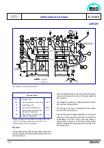
Water Mist Catcher
At outlet charge air cooler the charge air is led
through the water mist catcher. The water mist
catcher prevents condensed water (one of the major
causes of cylinder wear) from entering the combustion
chamber.
Turbocharger
The engine is as standard equipped with a high-
effeciency MAN B&W, NR/R turbocharger of the
radial type, which is located on the front end of the
engine, mounted on the top plate of the charging air
cooler housing.
Cleaning of Turbocharger
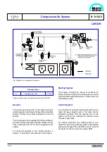
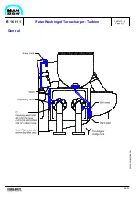
The turbocharger is fitted with an arrangement for
water washing of the turbine side, see B 16 01 1, and
water washing of the compressor side, see B 15 05
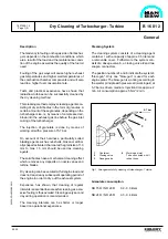
1. Soft blast cleaning on the turbine side can be fitted
as optional, see B 16 01 2.
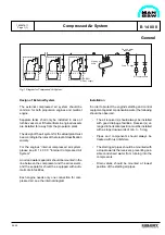
Lambda Controller
The purpose with the lambda controller is to prevent
injection of more fuel in the combustion chamber
than can be burned during a momentary load in-
crease. This is carried out by controlling the relation
between the fuel index and the charge air pressure.
The lambda controller has the following advantages:
–
Reduction of visible smoke in case of sudden
momentary load increases.
–
Improved load ability.
–
Less fouling of the engines exhaust gas ways.
Combustion Air System
L28/32H
99.48
1613523-1.4
Page 2 (2)
–
Limitating of fuel oil index during starting
procedure.
The above states that the working conditions are
improved under difficult circumstances and that the
maintenance expenses for an engine, working with
many and major load changes, will be reduced.
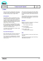
Optionals
Besides the standard components, the following
standard optionals can be built-on:
Pressure alarm low
–
PAL 35 Charge air, surplus air inlet
Pressure differential alarm low
–
PDAL 31-62, charge air and exhaust gas
Pressure transmitting
–
PT 31
Charge air, outlet from cooler
Temperature alarm high
–
TAH 31 Charge air, outlet from cooler
Temperature element
–
TE 31
Charge air, outlet from cooler
–
TE 60
Exhaust gas, outlet cylinder
–
TE 61
Exhaust gas, outlet turbocharger
–
TE 62
Exhaust gas, inlet turbocharger
Temperature indicating
–
TI 60
Exhaust gas, outlet cylinder
–
TI 61
Exhaust gas, outlet turbocharger
–
TI 62
Exhaust gas, inlet turbocharger
Data
For charge air heat dissipation and exhaust gas
data, see D 10 05 0 "List of Capacities".
Set points and operating levels for temperature and
pressure are stated in B 19 00 0 "Operating Data and
Set Points".
Содержание L28/32H
Страница 4: ......
Страница 5: ...Introduction I 00...
Страница 6: ......
Страница 8: ......
Страница 10: ......
Страница 11: ...Designation of Cylinders In Line 98 19 1607568 0 1 Page 1 1 I 00 15 0...
Страница 12: ......
Страница 18: ......
Страница 19: ...General information D 10...
Страница 20: ......
Страница 22: ......
Страница 24: ......
Страница 26: ......
Страница 30: ......
Страница 32: ......
Страница 34: ......
Страница 36: ......
Страница 37: ...Basic Diesel Engine B 10...
Страница 38: ......
Страница 44: ......
Страница 45: ...99 40 B 10 01 1 L28 32H Cross Section 1607528 5 2 Page 1 1...
Страница 46: ......
Страница 48: ......
Страница 50: ......
Страница 52: ......
Страница 54: ......
Страница 58: ......
Страница 59: ...1607566 7 1 Page 1 1 Engine Rotation Clockwise B 10 11 1 General 98 18...
Страница 60: ......
Страница 61: ...Fuel Oil System B 11...
Страница 62: ......
Страница 65: ...08028 0D H5250 94 08 12 General Fuel Oil Diagram B 11 00 0 1624468 9 4 Page 1 3 99 33 Fig 1 Fuel oil diagram...
Страница 68: ......
Страница 72: ......
Страница 74: ......
Страница 76: ......
Страница 79: ...Lubrication Oil System B 12...
Страница 80: ......
Страница 86: ......
Страница 88: ......
Страница 91: ...Cooling Water System B 13...
Страница 92: ......
Страница 98: ......
Страница 106: ......
Страница 108: ......
Страница 112: ......
Страница 113: ...Compressed Air System B 14...
Страница 114: ......
Страница 118: ......
Страница 119: ...Combustion Air System B 15...
Страница 120: ......
Страница 124: ......
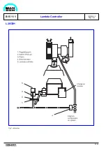
Страница 126: ...Fig 1 Jet system 1639456 5 0 Page 2 2 Lambda Controller 93 44 L28 32H B 15 11 1...
Страница 127: ...Exhaust Gas System B 16...
Страница 128: ......
Страница 132: ...08028 0D H5250 94 08 12 General 1607517 7 4 Page 2 2 Water Washing of Turbocharger Turbine B 16 01 1 98 20...
Страница 136: ......
Страница 140: ......
Страница 142: ......
Страница 144: ......
Страница 146: ......
Страница 147: ...Speed Control System B 17...
Страница 148: ......
Страница 150: ......
Страница 152: ......
Страница 153: ...Monitoring Equipment B 18...
Страница 154: ......
Страница 156: ......
Страница 158: ......
Страница 159: ...Safety and Control System B 19...
Страница 160: ......
Страница 164: ......
Страница 166: ......
Страница 177: ...Foundation B 20...
Страница 178: ......
Страница 180: ......
Страница 183: ...Test running B 21...
Страница 184: ......
Страница 186: ......
Страница 187: ...Spare Parts E 23...
Страница 188: ......
Страница 190: ......
Страница 191: ...99 35 1607521 2 6 Page 1 1 Recommended Wearing Parts E 23 04 0 L28 32H...
Страница 192: ......
Страница 195: ...Tools P 24...
Страница 196: ......
Страница 200: ......
Страница 202: ......
Страница 203: ...Preservation and Packing B 25...
Страница 204: ......
Страница 206: ......
Страница 208: ......
Страница 210: ......
Страница 211: ...Alternator G 50...
Страница 212: ......
Страница 216: ......
Страница 218: ......


