08028-0D\H5250\94.08.12
98.33
Description
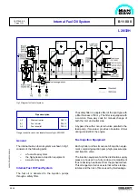
The fuel changing system consist for GenSet of two
three-way valves (V1 and V2) with a electric/
pneumatically operated actuator of the simplex type
with spring return and a common valve control box
for the total GenSet plant.
The system facilitates a flexible selection of MDO
and HFO-operating at any load condition. This sy-
stem gives the advantage of individually choosing
MDO or HFO mode of operation of the GenSets.
General
HFO/MDO Changing Valves (V1 and V2)
E 11 10 1
1624467-7.2
Page 1 (2)
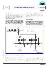
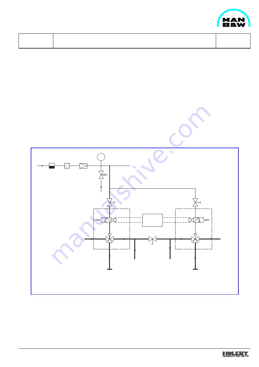
To maintain recirculation in the HFO flow line when
the GenSet is operated on MDO a by-pass valve
must be installed between the inlet changing valve
(V1) and the outlet valve (V2) at each GenSet as
shown in fig. 1.
Valve Control Box
Electrical power supply to the valve control box is
380 Volt - 50 Hz, or 440 Volt - 60 Hz, depending on
the plant specification, and is established in form of
a single cable connection from the switchboard.
PI
Filter
MDO
Valve V2
Outlet engine
Inlet engine
HFO
HFO
Valve V1
MDO
Reduction
valve
Water trap
Valve con-
trol box
Air pressure: 6 bar
Air consumption
per stroke : 1.1 litre
ø6
ø6
*
*
*
*
MAN B&W Supply
A1
A2
Due to a built-in transformer, the power supply
voltage will be converted to a 24 Volt DC pilot voltage
for serving the relays, contactors, and indication
lamps.
The three-way valves should be placed as near as
possible to the engines. The control box can be
placed in the engine room or in the engine control
room.
Fig. 1 Pneumatic diagram for 3-way changing valves V1 & V2.
Содержание L28/32H
Страница 4: ......
Страница 5: ...Introduction I 00...
Страница 6: ......
Страница 8: ......
Страница 10: ......
Страница 11: ...Designation of Cylinders In Line 98 19 1607568 0 1 Page 1 1 I 00 15 0...
Страница 12: ......
Страница 18: ......
Страница 19: ...General information D 10...
Страница 20: ......
Страница 22: ......
Страница 24: ......
Страница 26: ......
Страница 30: ......
Страница 32: ......
Страница 34: ......
Страница 36: ......
Страница 37: ...Basic Diesel Engine B 10...
Страница 38: ......
Страница 44: ......
Страница 45: ...99 40 B 10 01 1 L28 32H Cross Section 1607528 5 2 Page 1 1...
Страница 46: ......
Страница 48: ......
Страница 50: ......
Страница 52: ......
Страница 54: ......
Страница 58: ......
Страница 59: ...1607566 7 1 Page 1 1 Engine Rotation Clockwise B 10 11 1 General 98 18...
Страница 60: ......
Страница 61: ...Fuel Oil System B 11...
Страница 62: ......
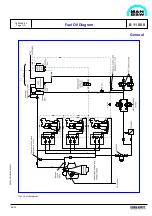
Страница 65: ...08028 0D H5250 94 08 12 General Fuel Oil Diagram B 11 00 0 1624468 9 4 Page 1 3 99 33 Fig 1 Fuel oil diagram...
Страница 68: ......
Страница 72: ......
Страница 74: ......
Страница 76: ......
Страница 79: ...Lubrication Oil System B 12...
Страница 80: ......
Страница 86: ......
Страница 88: ......
Страница 91: ...Cooling Water System B 13...
Страница 92: ......
Страница 98: ......
Страница 106: ......
Страница 108: ......
Страница 112: ......
Страница 113: ...Compressed Air System B 14...
Страница 114: ......
Страница 118: ......
Страница 119: ...Combustion Air System B 15...
Страница 120: ......
Страница 124: ......
Страница 126: ...Fig 1 Jet system 1639456 5 0 Page 2 2 Lambda Controller 93 44 L28 32H B 15 11 1...
Страница 127: ...Exhaust Gas System B 16...
Страница 128: ......
Страница 132: ...08028 0D H5250 94 08 12 General 1607517 7 4 Page 2 2 Water Washing of Turbocharger Turbine B 16 01 1 98 20...
Страница 136: ......
Страница 140: ......
Страница 142: ......
Страница 144: ......
Страница 146: ......
Страница 147: ...Speed Control System B 17...
Страница 148: ......
Страница 150: ......
Страница 152: ......
Страница 153: ...Monitoring Equipment B 18...
Страница 154: ......
Страница 156: ......
Страница 158: ......
Страница 159: ...Safety and Control System B 19...
Страница 160: ......
Страница 164: ......
Страница 166: ......
Страница 177: ...Foundation B 20...
Страница 178: ......
Страница 180: ......
Страница 183: ...Test running B 21...
Страница 184: ......
Страница 186: ......
Страница 187: ...Spare Parts E 23...
Страница 188: ......
Страница 190: ......
Страница 191: ...99 35 1607521 2 6 Page 1 1 Recommended Wearing Parts E 23 04 0 L28 32H...
Страница 192: ......
Страница 195: ...Tools P 24...
Страница 196: ......
Страница 200: ......
Страница 202: ......
Страница 203: ...Preservation and Packing B 25...
Страница 204: ......
Страница 206: ......
Страница 208: ......
Страница 210: ......
Страница 211: ...Alternator G 50...
Страница 212: ......
Страница 216: ......
Страница 218: ......

