08028-0D/H5250/94.08.12
ü
ï
ï
ï
ï
ï
ï
ý
ï
ï
ï
ï
ï
ï
ï
þ
1631457-0.0
Page 1 (2)
Engine Control Box
E 19 06 4
General
The Safety System
The engine control box is watching the most
important safety operating functions of the diesel
engine, i.e. low lub. oil pressure, high cooling water
temperature, and overspeed.
If an unintended condition occurs to one of the above
functions, the engine control box will release
automatic stop of the engine (shut-down).
In order to avoid an unintended re-starting after
release of a shut-down, there is a built-in reset
function which has to be activated before the engine
can be re-started. Remote reset is also possible.
Besides, there are built-in start/stop procedures for
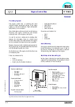
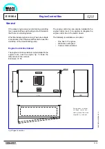
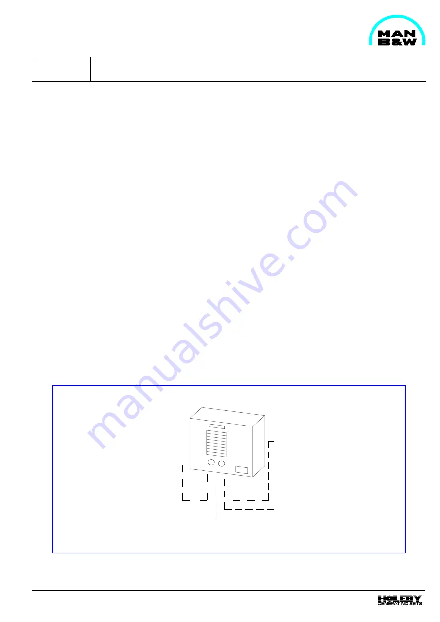
the engine. On fig. 1 the possible external connections
and input/output signals are shown.
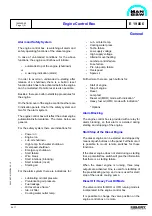
On the front cover of the engine control box there are
an indication panel.
There are indications for:
-
Power
-
Lub. oil shutdown
-
High temp. fresh water shutdown
92.25
ì
ï
í
î
Power supply
24 V DC, 6 A ±20%
Input from engine
-
Engine run signal
-
Pressurestate PSL 22 lub.oil
pressure low - shut-down
-
Thermostate TSH 12 cooling
water - shut-down
-
Microswitch SSH 81 speed
high - Shut-down
-
Stop
-
Start interlock
ì
ï
ï
ï
í
ï
ï
ï
î
Output to engine
-
Power supply
-
Stop signal - shut-down solenoid
-
Start signal
Fig 1 External connections to/from the engine control box .
-
Overspeed shutdown
-
Start failure
-
Wire break
-
Start interlocks
There are push buttons for:
-
Start
-
Stop
-
Reset
-
Lamp test
Alarm Blocking
The engine control box is provided with a relay output
for alarm blocking. It is advisable to use in case of
too low lub. oil pressure, so that alarm is avoided
during starting and stopping of the engines.
Start/Stop of the Diesel Engine
As the engine control box can give the diesel engine
a signal of normal start/stop, it is possible to mount
remote switches for these functions.
From main switch board
-
Start signal
-
Stop signal
-
Emergency stop signal
-
Reset signal
To main switch board
-
Common shutdown
-
Start failure
-
Power failure
-
Cable failure
-
Alarm blocking
-
Engine run
To pre.lub. oil pump starter
-
Start/stop signal
Содержание L28/32H
Страница 4: ......
Страница 5: ...Introduction I 00...
Страница 6: ......
Страница 8: ......
Страница 10: ......
Страница 11: ...Designation of Cylinders In Line 98 19 1607568 0 1 Page 1 1 I 00 15 0...
Страница 12: ......
Страница 18: ......
Страница 19: ...General information D 10...
Страница 20: ......
Страница 22: ......
Страница 24: ......
Страница 26: ......
Страница 30: ......
Страница 32: ......
Страница 34: ......
Страница 36: ......
Страница 37: ...Basic Diesel Engine B 10...
Страница 38: ......
Страница 44: ......
Страница 45: ...99 40 B 10 01 1 L28 32H Cross Section 1607528 5 2 Page 1 1...
Страница 46: ......
Страница 48: ......
Страница 50: ......
Страница 52: ......
Страница 54: ......
Страница 58: ......
Страница 59: ...1607566 7 1 Page 1 1 Engine Rotation Clockwise B 10 11 1 General 98 18...
Страница 60: ......
Страница 61: ...Fuel Oil System B 11...
Страница 62: ......
Страница 65: ...08028 0D H5250 94 08 12 General Fuel Oil Diagram B 11 00 0 1624468 9 4 Page 1 3 99 33 Fig 1 Fuel oil diagram...
Страница 68: ......
Страница 72: ......
Страница 74: ......
Страница 76: ......
Страница 79: ...Lubrication Oil System B 12...
Страница 80: ......
Страница 86: ......
Страница 88: ......
Страница 91: ...Cooling Water System B 13...
Страница 92: ......
Страница 98: ......
Страница 106: ......
Страница 108: ......
Страница 112: ......
Страница 113: ...Compressed Air System B 14...
Страница 114: ......
Страница 118: ......
Страница 119: ...Combustion Air System B 15...
Страница 120: ......
Страница 124: ......
Страница 126: ...Fig 1 Jet system 1639456 5 0 Page 2 2 Lambda Controller 93 44 L28 32H B 15 11 1...
Страница 127: ...Exhaust Gas System B 16...
Страница 128: ......
Страница 132: ...08028 0D H5250 94 08 12 General 1607517 7 4 Page 2 2 Water Washing of Turbocharger Turbine B 16 01 1 98 20...
Страница 136: ......
Страница 140: ......
Страница 142: ......
Страница 144: ......
Страница 146: ......
Страница 147: ...Speed Control System B 17...
Страница 148: ......
Страница 150: ......
Страница 152: ......
Страница 153: ...Monitoring Equipment B 18...
Страница 154: ......
Страница 156: ......
Страница 158: ......
Страница 159: ...Safety and Control System B 19...
Страница 160: ......
Страница 164: ......
Страница 166: ......
Страница 177: ...Foundation B 20...
Страница 178: ......
Страница 180: ......
Страница 183: ...Test running B 21...
Страница 184: ......
Страница 186: ......
Страница 187: ...Spare Parts E 23...
Страница 188: ......
Страница 190: ......
Страница 191: ...99 35 1607521 2 6 Page 1 1 Recommended Wearing Parts E 23 04 0 L28 32H...
Страница 192: ......
Страница 195: ...Tools P 24...
Страница 196: ......
Страница 200: ......
Страница 202: ......
Страница 203: ...Preservation and Packing B 25...
Страница 204: ......
Страница 206: ......
Страница 208: ......
Страница 210: ......
Страница 211: ...Alternator G 50...
Страница 212: ......
Страница 216: ......
Страница 218: ......

