08028-0D\H5250\94.08.12
B 13 00 0
Freshwater System Treatment
1609571-3.4
Page 3 (5)
General
00.11
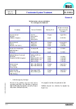
A chloride content in the cooling water higher than
the 50 ppm specified might, in exceptional cases be
tolerated. However, in that case the upper limit
specified by the individual inhibitor supplier must not
be exceed.
A clear record of all measuring results should be
kept, so that the actual condition and trend of the
system may be currently ascertained and evaluated.
A sudden or gradual degrease in pH value, or an
increase of the sulphate content, may indicate ex-
haust gas leakage. The pH value can be increased
by adding inhibtor; however, if major quantities are
necessary, the water should be replaced.
Every third month a cooling water sample should be
sent ashore for laboratory analysis, in particular to
ascertain the contents of inhibtor, sulphate, and iron,
as well as the total salinity of the water.
Cleaning and Inhibiting Procedure
The engine must not be running during the cleaning
procedure, as this may involve the risk of overhea-
ting when draining.
Degreasing
Use clean tap water for filling-up. The cooling water
in the system can be used, if it does not contain
inhibitors.
Heat the water to 60° C and circulate the water
continuously.
Drain to lowest water level in expansion tank.
Add the amount of degreasing chemical specified by
the supplier, preferably from the suction side of the
freshwater pump.
Drain to lowest water level in the expansion tank
directly afterwards.
Circulate the cleaning chemical for the period speci-
fied by the supplier.
The cooling water system must not be kept
under pressure.
Check, and repair any leaks.
Drain the system and fill up completely with clean tap
water, in order to flush out any oil or grease from the
tank.
Circulate the water for 2 hours, and drain again.
Descaling with Acid Solution
Fill up with clean tap water and heat to 70-75° C.
Dissolve the necessary dosage of acid compound in
a clean iron drum with hot water.
Fill the drum half up with water and slowly add the
acid compound, while stirring vigorously. Then fill
the drum up completely with hot water while conti-
nuing to stir (e.g. using a steam hose).
Be careful - use protective spectacles and gloves.
For engines which have been treated before the trial
trip, the lowest concentration recommended by the
supplier will normally be sufficient.
For untreated engines, a higher concentration -
depending on the condition of the cooling system -
will normally be necessary.
Drain some water from the system and add the acid
solution via the expansion tank.
The cooling water system must not be put under
pressure.
Keep the temperature of the water between 70° C
and 75° C, and circulate it constantly. The duration
of the treatment will depend on the degree of fouling.
Normally, the shortest time recommended by the
supplier will be sufficient for engines which are
treated before the trial trip. For untreated engines, a
longer time must be reckoned with. Check every
hour, for example with pH-paper, that the acid in the
solution has not been used up.
Содержание L28/32H
Страница 4: ......
Страница 5: ...Introduction I 00...
Страница 6: ......
Страница 8: ......
Страница 10: ......
Страница 11: ...Designation of Cylinders In Line 98 19 1607568 0 1 Page 1 1 I 00 15 0...
Страница 12: ......
Страница 18: ......
Страница 19: ...General information D 10...
Страница 20: ......
Страница 22: ......
Страница 24: ......
Страница 26: ......
Страница 30: ......
Страница 32: ......
Страница 34: ......
Страница 36: ......
Страница 37: ...Basic Diesel Engine B 10...
Страница 38: ......
Страница 44: ......
Страница 45: ...99 40 B 10 01 1 L28 32H Cross Section 1607528 5 2 Page 1 1...
Страница 46: ......
Страница 48: ......
Страница 50: ......
Страница 52: ......
Страница 54: ......
Страница 58: ......
Страница 59: ...1607566 7 1 Page 1 1 Engine Rotation Clockwise B 10 11 1 General 98 18...
Страница 60: ......
Страница 61: ...Fuel Oil System B 11...
Страница 62: ......
Страница 65: ...08028 0D H5250 94 08 12 General Fuel Oil Diagram B 11 00 0 1624468 9 4 Page 1 3 99 33 Fig 1 Fuel oil diagram...
Страница 68: ......
Страница 72: ......
Страница 74: ......
Страница 76: ......
Страница 79: ...Lubrication Oil System B 12...
Страница 80: ......
Страница 86: ......
Страница 88: ......
Страница 91: ...Cooling Water System B 13...
Страница 92: ......
Страница 98: ......
Страница 106: ......
Страница 108: ......
Страница 112: ......
Страница 113: ...Compressed Air System B 14...
Страница 114: ......
Страница 118: ......
Страница 119: ...Combustion Air System B 15...
Страница 120: ......
Страница 124: ......
Страница 126: ...Fig 1 Jet system 1639456 5 0 Page 2 2 Lambda Controller 93 44 L28 32H B 15 11 1...
Страница 127: ...Exhaust Gas System B 16...
Страница 128: ......
Страница 132: ...08028 0D H5250 94 08 12 General 1607517 7 4 Page 2 2 Water Washing of Turbocharger Turbine B 16 01 1 98 20...
Страница 136: ......
Страница 140: ......
Страница 142: ......
Страница 144: ......
Страница 146: ......
Страница 147: ...Speed Control System B 17...
Страница 148: ......
Страница 150: ......
Страница 152: ......
Страница 153: ...Monitoring Equipment B 18...
Страница 154: ......
Страница 156: ......
Страница 158: ......
Страница 159: ...Safety and Control System B 19...
Страница 160: ......
Страница 164: ......
Страница 166: ......
Страница 177: ...Foundation B 20...
Страница 178: ......
Страница 180: ......
Страница 183: ...Test running B 21...
Страница 184: ......
Страница 186: ......
Страница 187: ...Spare Parts E 23...
Страница 188: ......
Страница 190: ......
Страница 191: ...99 35 1607521 2 6 Page 1 1 Recommended Wearing Parts E 23 04 0 L28 32H...
Страница 192: ......
Страница 195: ...Tools P 24...
Страница 196: ......
Страница 200: ......
Страница 202: ......
Страница 203: ...Preservation and Packing B 25...
Страница 204: ......
Страница 206: ......
Страница 208: ......
Страница 210: ......
Страница 211: ...Alternator G 50...
Страница 212: ......
Страница 216: ......
Страница 218: ......


