
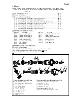


P 6 / 13
[3] -4. Disassembling/ Assembling of Clutch Case Section (cont.)
[3] -5. Disassembling/ Assembling of Clutch Section
Note: When repairing Clutch section, it is recommended to entirely replace Clutch assembly with fresh one.
However, if required to replace component parts of Clutch assembly, follow the disassembling/assembling
procedure described below
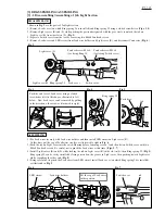
[3] -6. Disassembling/ Assembling of Gear case Section
DISASSEMBLING
1) Remove Clutch case section, and take Clutch section out of
the machine. (Refer to [3]-1, 3, 4.)
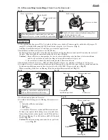
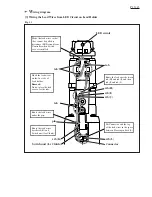
2) Insert Torque adjust toll into the hole of Adjust ring complete,
and turn it counterclockwise to remove Lock nut M12.
Decrease in the pressure of Compression spring 19 allows
you to remove Lock nut M12 by turning it clockwise by
hand. (Fig. 17)
3) Remove Adjust ring complete, Flat washer and Compression
spring 19 from Spindle.
4) While shifting the positions of Cam A and Cam D, replace
Steel ball 3.0 (13 pcs.), Steel ball 4.0 (3 pcs.)
and Steel ball 5.0 (3 pcs.).
Steel balls can be removed easily by using a magnet.
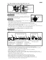
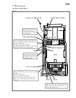
DISASSEMBLING
1) Remove Switch lever, Switch cover and Compression spring 2. (Refer to [3] -1.)
2) Remove four M4x22 Pan head screws to separate Clutch case from the machine.
3) Remove seven M3x20 Pan head screws to separate Housing (L) from (R).
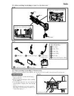
4) Remove switch unit from Gear case.
5) Separate Gear case section from Motor control unit by lifting up them, then turning
Motor bracket counterclockwise. (Fig. 19)
6) Pull off Motor bracket from Rotor, and then pull off Rotor from Motor control unit.
7) Remove Lock washer located in Gear case by turning counterclockwise with pliers
or slotted screwdriver. (Fig. 20)
8) Remove Spur gears, Internal gear, Carrier complete and Ball bearing 6805LLB.
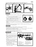
ASSEMBLING
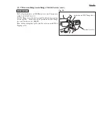
1) Press-fit Ball bearing 6000DDW to Spur gear 21 using arbor press and 1R033 or the like,
then install Retaining ring S-10 on Spur gear 21.
2) Into Clutch case, insert first Ball bearing 6803ZZ, next Flat washer 21, and third Spur gear 21.
Then install Retaining ring R-26.
Remark: Remember to place Compression spring 5 between Clutch case and Clutch assembly.
3) Put an appropriate amount of Makita seal lubricant in the hole on Spur gear 21. (Fig. 1)
ASSEMBLING
1) Apply Makita seal lubricant No. 101 to Steel ball 5.0
(3 pcs.), Steel ball 4.0 (3 pcs.) and Steel ball 3.0
(13 pcs.), and set these Steel balls in place on the Cams.
(Fig. 18)
2) Apply Makita seal lubricant No. 101 to the male threads
on Spindle, and then assemble Compression spring 19,
Flat washer and Adjust ring complete to Spindle,
and then secure Lock nut M12 to Spindle by turning it
counterclockwise using Torque adjust tool, etc.
Steel ball 3.0 (13 pcs)
Threads on Spindle
Steel ball 5.0 (3 pcs)
Steel ball 4.0 (3 pcs)
Cam A
Cam D
Fig. 18
Turn Torque adjust tool
counterclockwise.
Lock nut M12
Adjust ring complete
Cam D
Cam A
Compression spring 19
Flat washer
Fig. 17


