manualshive.com logo in svg
background image

P 5 / 13

[3] -3. Disassembling/ Assembling/ Adjustment of Angle Head Section (cont.)

[3] -4. Disassembling/ Assembling of Clutch Case Section
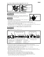
ASSEMBLING

1) Assemble Needle bearing 1212, Thin washer 12 and Spacer to Spiral
    bevel gear 9.
    Caution: Spacer is not reversible when assembled to Spiral bevel gear 9.
                    Be sure to place as illustrated in Fig. 11.
2) Press-fit Ball bearing 6900LLB to Spiral bevel gear 9 using arbor press
    and 1R033.  Assemble Retaining ring S-14 to Spiral bevel gear 9
    to complete assembling of Spiral bevel gear 9 section.
    And then insert Spiral bevel gear 9 section into Angle head complete.
3) Assemble Retaining ring R-22 to Spiral bevel gear 9.
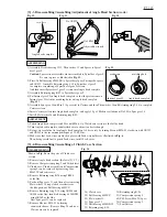
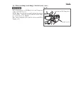
4) Put Internal gear 50 in Angle head complete so that the protrusions on
    Internal gear 50 fit in the matching holes on Angle head complete.
    (Fig. 15)
5) Assemble Spur gear 14 and Pin 3 (5 pcs each) to Carrier, and then Thin washer 14 and Retaining ring S-14 to complete
    Carrier section.
6) Insert Carrier section into Angle head complete, and apply 1.5g of Makita seal lubricant No.101 to Spur gear 14.
7) Install Flat washer 26 and Retaining ring R-32.
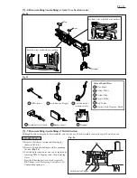
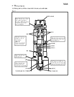
DISASSEMBLING

*Shown in Fig. 16 are the parts of Clutch case
  section.
1) Remove Angle head section. (Refer to [3]-1, 3.)
2) Remove Compression spring 2 and Switch lever.
3) Clutch case, Clutch assembly and Compression
    spring 5 can be removed by removing four
    M4x22 Pan head screws.
4) Remove Retaining ring R-26 using 1R006
    or the like.
5) Push out Spur gear 21, and then, after removing
    Flat washer 21 using slotted screwdriver or
    the like, push out Ball bearing 6803ZZ.
6) Remove Retaining ring S-10 using 1R004 and
    1R008 or the like, then Ball bearing 6000DDW
     using 1R269 or the like.
     Now Spur gear 21 can be replaced.
7) Remove Hex nut M36-41 by turning
     counterclockwise.   Remove Ring 38, and now
     Clutch case can be replaced.
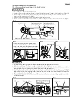
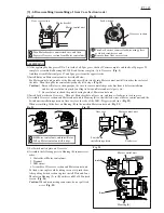
ADJUSTMENT

1) Fasten Angle head complete and Hex nut M36-41 to Clutch case section to the full by hand.
2) Turn Angle head complete counterclockwise to adjust to a desired angle.
3) Being very careful not to turn Angle head complete, fix it securely by turning Hex nut M36-41 clockwise with 1R223
    and 1R341 to the recommended torque of 30 -50N.m.
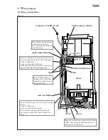
4) Make sure that Lead wires are fixed in place with Lead wire holders as illustrated in Fig. 6.
    Then, being careful not to pinch Lead wires, install Lead cover.

Fig. 12

Fig. 13

Fig. 14

Fig. 15

Fig. 16

Angle head complete

two flats

Adjustable wrench

No.1R223

No.1R341

protrusion

Internal gear 50

matching hole

Angle head complete

28) Clutch case
29) Ball bearing 6803ZZ
30) Flat washer 21
31) Spur gear 21
32) Ball bearing 6000DDW
33) Retaining ring S-10

34) Retaining ring R-26
35) Compression spring 5
69) P.H. Screw M4x22 (4pcs)
70) Compression spring 2
71) Switch lever

28

29 30

31

32 33

34

35

69

70

71

Содержание BFL300F

Страница 1: ...harger BFL300F Dimensions mm Model No Length L Height H Width W BFL400F BFL401F 506 20 510 20 1 16 104 4 1 8 73 2 7 8 104 4 1 8 73 2 7 8 Center height CH Head height HH 16 5 8 31 5 1 1 4 18 11 16 34 1...

Страница 2: ...19 Torque Wrench Shaft 7 23N m 1R220 Ratchet Head 9 5 1R222 Socket Adapter Code No Tool Name 1R223 Torque Wrench Shaft 20 90N m 1R269 Bearing Extractor 1R291 Retaining Ring S and R Pliers 1R341 Spanne...

Страница 3: ...ircuit on Light cover R At this time put the sag of Lead wires in place as illustrated to right in Fig 6 2 Push the tab on Light cover into the cut in Housing before fastening screws And then fasten S...

Страница 4: ...mping Bearing retainer be very careful not to deform it by overtightening 3 Remove Angle head complete by turning counterclockwise 4 Remove Retaining ring R 32 using 1R006 or the like then Flat washer...

Страница 5: ...se Clutch assembly and Compression spring 5 can be removed by removing four M4x22 Pan head screws 4 Remove Retaining ring R 26 using 1R006 or the like 5 Push out Spur gear 21 and then after removing F...

Страница 6: ...section from Motor control unit by lifting up them then turning Motor bracket counterclockwise Fig 19 6 Pull off Motor bracket from Rotor and then pull off Rotor from Motor control unit 7 Remove Lock...

Страница 7: ...Housing R so that the lead wires of Motor control unit and the Switch unit installation portion on Gear case face the side of the LED Trigger switch line Fig 22 When assembling fit the boss on Housing...

Страница 8: ...rts can also be replaced F R Change lever Leaf spring Switch lever A Compression spring A Although Switch section can be disassembled you can also use Switch assembly to entirely replace Switch sectio...

Страница 9: ...mpression spring 4 on Switch lever A Put F R Change lever Switch lever and Switch unit for rotation reverse in place At this time fit the protrusion on F R Change lever in Switch lever A Fig 27 Then w...

Страница 10: ...ain switch Switch unit B for rotation reverse Switch unit A for Trigger Switch unit C for clutch LED circuit for job light LED PWB for display Buzzer circuit Color index of lead wires sheath Black Whi...

Страница 11: ...Controller to Buzzer between the ribs on Controller Place Connectors and the sag of lead wires in the space between ribs A B C and pins rib D boss Controller Route the lead wires orange white blue fr...

Страница 12: ...D circuit wires to switch unit for Clutch At this time place the lead wires so that the tape is positioned beside Printed wiring board pin rib G rib F rib E Connector Stator Route the six lead wires o...

Страница 13: ...Make the lead wires so that they cannot be pulled to disconnect LED circuit from Controller when Switch cover is installed 3 Wiring the Lead Wires from LED Circuit on Lead Holder Connector Switch unit...

Отзывы: