
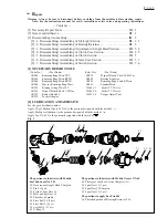


P 4 / 13
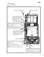
[3] -1. Disassembling/ Assembling of Job Light Section (cont.)
[3] -2. Disassembling/ Assembling of Bearing Retainer
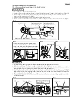
Fig. 8
Fig. 9
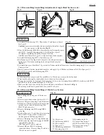
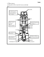
Fig. 11
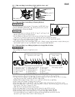
Fig. 10
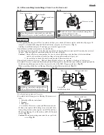
DISASSEMBLING
ASSEMBLING
1) After applying Makita seal lubricant No.101 to O ring 15, put O ring 15 and
Bearing retainer in place on Spindle complete.
2) Put 2g of Makita seal lubricant No.101 in the gear room of Angle head complete.
At this time, be careful not to put the grease on the threaded portion of Angle head complete.
3) Apply Loctite 603 to the threaded portion of Bearing retainer, and screw it into Angle head complete.
At this time, remember to put Flat washer 5 in place.
4) Fasten Bearing retainer to the recommended torque of 30 - 50N.m by turning counterclockwise with the following tools;
1R219, 1R220, 1R222, 134844-7 (for BFL300F), 134848-9 (for BFL400F/ BFL401F)
Turn Bearing retainer clockwise using a 27mm spanner for BFL300F/ 32mm
spanner for BFL400F and BFL401F. Now Bearing retainer can be removed
by pushing it down as illustrated in Fig. 10.
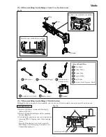
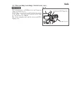
DISASSEMBLING
1) Remove Light covers (R) and (L), Ring spring 29, Lead cover and Switch cover. (Refer to [3] -1.)
2) Fix Angle head by clamping its two flats using adjustable wrench or vise, and remove Hex nut M36-41 by turning
in the direction of the arrow with 1R223 and 1R341. (Figs. 12, 13)
Caution: When clamping Bearing retainer, be very careful not to deform it by overtightening.
3) Remove Angle head complete by turning counterclockwise.
4) Remove Retaining ring R-32 using 1R006 or the like, then Flat washer 26, Internal gear 50 and Carrier section.
5) Remove Retaining ring S-14 from Carrier section using 1R291 or the like. Now the following parts can be replaced;
Flat washer 14, Pin 3 (5pcs), Spur gear 14 (5pcs)
Note: Pin 3 can be pulled out easily by using a magnet.
6) Remove Retaining ring R-22 located inside Angle head complete using 1R005 or the like.
7) Remove Spiral bevel gear 9 section by hitting the end face of Angle head complete. (Fig. 14)
8) Remove Retaining ring S-10 from Spiral bevel gear 9 section using 1R004, 1R008 or the like.
Now the following parts can be replaced by removing Ball bearing 6900LLB with 1R269 or the like:
Spiral bevel gear 9, Spacer, Thin washer 12, Needle bearing 1212
Ring spring 29
Lead cover
Lead wire
Ring spring 36
Bearing retainer
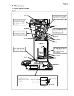
[3] -3. Disassembling/ Assembling/ Adjustment of Angle Head Section
10) Angle head complete
11) Spiral bevel gear 9
12) Needle bearing 1212
13) Thin washer 12
14) Spacer
15) Ball bearing 6900LLB
16) Retaining ring S-10
17) Retaining ring R-22
18) Internal gear 50
19) Retaining ring S-14
20) Flat washer 14
21) Pin 3 (5pcs)
22) Spur gear 14 (5pcs)
23) Carrier
24) Flat washer 26
25) Retaining ring R-32
*Shown in Fig. 11 are the parts of Angle head section.
10
11
12
13
14
15
16
17
18
19 20
23
24
25
21 22
Spiral bevel gear 9 section
Carrier section


