background image

15

WARNING - Maintenance

1. 

Have the product serviced by a qualified repair person using 

only identical replacement parts.

 This will ensure that the safety 

of the product is maintained.

2. 

Never service damaged battery packs.

 Service of battery packs 

should only be performed by the manufacturer or authorized 

service providers.

3. 

Follow instruction for changing accessories.

4. 

Do not disassemble, repair, modify or retrofit this product, 

charger or battery.

 Doing so might cause ignition or abnormal 

operation, which may result in injury.

5. 

Inspect this product for damaged parts.

 If this product is 

operating abnormally or malfunctioning, immediately stop use. 

Continued use of this product in this condition might lead to smoke 

emission, ignition, electric shock, or injury.

<Examples of Abnormalities and Malfunction>

x Power cable and power plug are abnormally hot.
x The power cable has deep scratches or is deformed.
x Power turns ON and OFF when the power cable is moved.

x There is a burning smell.
x There is a tingling feeling of electricity.

If you sense a malfunction, such as this product not functioning 

even after turning the power switch ON, immediately remove 

the battery and ask the store of purchase or a Makita authorized 

service center for inspection and repair.

6. 

This product complies with relevant safety standard.

 Do not 

modify or retrofit it.

7. 

If repair is performed by a person without specialist 

knowledge and repair skills, not only will the performance 

of this product not be fully demonstrated but this might also 

result in accident or injury.

Содержание 0088381724142

Страница 1: ...INSTRUCTION MANUAL Rechargeable Wall Scanner DWD181 ENGLISH Original instructions Read before use ...

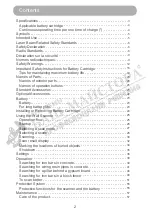
Страница 2: ...tandard Accessories 21 Optional Accessories 22 Battery 23 Battery 23 For long battery life 23 Installing or Removing Battery Cartridge 24 Using the Wall Scanner 25 Operation flow 25 Startup 26 Selecting a scan mode 27 Selecting a scene 28 Scanning 30 Scan result display 32 Marking the locations of buried objects 34 Shutdown 35 Settings 36 Operation 39 Searching for iron bars in concrete 39 Searchi...

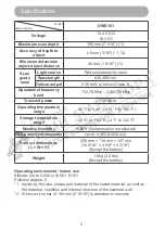
Страница 3: ...g temperature range 10 C to 40 C 14 F to 104 F Storage temperature range 20 C to 50 C 4 F to 122 F Relative Humidity 5 60 Condensation not allowed ESD protective measures Level 4 IEC61000 4 2 Product dimensions L W H 259 mm 118 mm 107 mm 10 3 16 4 5 8 4 3 16 Except the battery Weight 1 0 kg 2 2 lbs Except the battery Operating environment Indoor use Altitude Up to 2 000 m 6 561 11 16 Pollution deg...

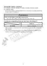
Страница 4: ...Only use the battery cartridges listed above Use of any other battery cartridges may cause injury and or fire Continuous operating time per one time of charge Model Battery DWD181 BL1860B Approx 28 hours Major functions shapes and other specifications are subject to change for improvement The continuous operating time is for reference purposes It varies by the battery s charge status and the opera...

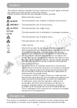
Страница 5: ...ave reached the end of their life must be collected separately and returned to an environmentally compatible recycling facility Li ion Only for EU countries Due to the presence of hazardous components in the equipment waste electrical and electronic equipment accumulators and batteries may have a negative impact on the environment and human health Do not dispose of electrical and electronic applia...

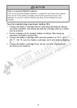
Страница 6: ... the BL1415N BL1430B BL1460B BL1815N BL1820B BL1830B BL1840B BL1850B BL1860B battery cartridge This caution is an explanation for labels used on this product Use only the genuine Makita batteries listed above Use of non genuine Makita batteries or batteries that have been altered may result in the battery bursting causing fires personal injury and damage It will also void the Makita warranty for t...

Страница 7: ...y interference received including interference that may cause undesired operation Section 15 525 Coordination requirements a UWB imaging systems require coordination through the FCC before the equipment may be used The operator shall comply with any constraints on equipment usage resulting from this coordination b The users of UWB imaging devices shall supply operational areas to the FCC Office of...

Страница 8: ... required provided the reported areas of operation do not change If the area of operation changes updated information shall be submitted to the FCC following the procedure in paragraph b of this section f The coordination of routine UWB operations shall not take longer than 15 business days from the receipt of the coordination request by NTIA Special temporary operations may be handled with an exp...

Страница 9: ...akita d origine listées ci dessus Les batteries autres que celles fabriquées par Makita ou les batteries modifiées peuvent exploser et causer un incendie une blessure ou des dommages Leur usage annulerait également la garantie Makita fournie pour l appareil et le chargeur Normes radioélectriques FCC partie 15 sous partie B Federal Communications Commission FCC Equipment authorization of unintentio...

Страница 10: ...rait causer un fonctionnement indésirable Section 15 525 Obligation de coordination a Les systèmes d imagerie UWB nécessitent une coordination en passant par la FCC avant que les équipements puissent être utilisés L opérateur devra respecter les restrictions aux emplois des équipements qui résultent de cette coordination b Les utilisateurs des appareils d imagerie UWB devront communiquer des zones...

Страница 11: ...angeront pas Si la zone d utilisation change des informations mises à jour devront être soumises à la FCC en suivant la procédure décrite au paragraphe b de la présente section f La coordination des opérations UWB de routine ne devra pas prendre plus de 15 jours ouvrés à compter de la réception de la demande de coordination par NTIA Des opérations temporaires particulières pourront être traitées d...

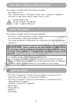
Страница 12: ...f your eyes might be impaired immediately seek treatment by a physician CAUTION Laser light is bright and blinding Do not shine at aircraft or vehicles at any distance WARNING Work area safety 1 Keep work area clean and well lit Cluttered or dark areas invite accidents 2 Do not operate the product in explosive atmospheres such as in the presence of flammable liquids gases or dust Products create s...

Страница 13: ...hock if your body is earthed or grounded 2 Do not expose the product to rain wet conditions or humid conditions Water entering the product will increase the risk of electric shock 3 Do not short circuit terminals on the product Do not allow pins or wire to get inside the USB terminal This may cause a short circuit which may result in the risk of smoke emission or ignition 4 Do not hold the power s...

Страница 14: ...minals together may cause burns or a fire 5 Under abusive conditions liquid may be ejected from the battery avoid contact If contact accidentally occurs flush with water If liquid contacts eyes additionally seek medical help Liquid ejected from the battery may cause irritation or burns 6 Do not use a battery pack or product that is damaged or modified Damaged or modified batteries may exhibit unpr...

Страница 15: ...oduct in this condition might lead to smoke emission ignition electric shock or injury Examples of Abnormalities and Malfunction x Power cable and power plug are abnormally hot x The power cable has deep scratches or is deformed x Power turns ON and OFF when the power cable is moved x There is a burning smell x There is a tingling feeling of electricity If you sense a malfunction such as this prod...

Страница 16: ...side the wall structure etc Even if the wall scanner indicates that there is no object an object may actually be buried causing a danger for drilling and other types of work 5 Before working on the structure such as by cutting and drilling be sure to see architectural drawings and other information in addition to the scan results of the wall scanner 6 A great change in the ambient temperature duri...

Страница 17: ...tion manual contact the store of your purchase or a Makita sales office to make a repair request For switch malfunctions contact the store of your purchase or a Makita sales office to make a repair request When abnormality or malfunction is found stop using the product immediately Continued use may result in smoke ignition electric sock and or injury Abnormality and malfunction examples The produc...

Страница 18: ... is severely damaged or is completely worn out The battery cartridge can explode in a fire 8 Be careful not to drop or strike battery 9 Do not use a damaged battery 10 The contained lithium ion batteries are subject to the Dangerous Goods Legislation requirements For commercial transports e g by third parties forwarding agents special requirement on packaging and labeling must be observed For prep...

Страница 19: ...um battery life 1 Charge the battery cartridge before completely discharged Always stop tool operation and charge the battery cartridge when you notice less tool power 2 Never recharge a fully charged battery cartridge Overcharging shortens the battery service life 3 Charge the battery cartridge with room temperature at 10 C 40 C 50 F 104 F Let a hot battery cartridge cool down before charging it ...

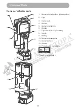
Страница 20: ... 11 13 1 Sensor s left edge line right edge line 2 Light 3 Guide laser 4 Wheels 5 Sensor s center line 6 Display 7 Operation buttons 6 buttons 8 Handle 9 Battery 10 Sensor s center point 11 Sensor surface 12 Wheels 13 Product label nameplate Product of laser class 1 ...

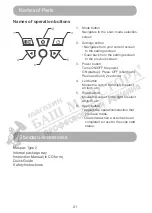
Страница 21: ...ns ON OFF the power ON startup Press OFF shutdown Press and hold 2 seconds 4 Left button Moves the cursor to the left to select an item etc 5 Right button Moves the cursor to the right to select an item etc 6 Apply button Applies the operation selection that you have made Clears data when a scan has been completed to reset to the scan start status Standard Accessories Makpac Type 2 Internal packag...

Страница 22: ... in this manual The use of any other accessories or attachments might present a risk of injury to persons Only use accessory or attachment for its stated purpose If you need any assistance for more details regarding these accessories ask your local Makita Service Center Makita genuine battery and charger NOTE Some items in the list may be included in the tool package as standard accessories They m...

Страница 23: ...rom water and dust When the product is not used store it with the battery removed For long battery life After the battery change mark is turned on stop using the battery and charge it Do not recharge the battery when fully charged Charge the battery in the ambient temperature range of 10 C 40 C 50 F 104 F When the battery is hot such as when it has just used we recommend that it be cooled down in ...

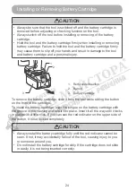
Страница 24: ...olored section 2 Button 3 Battery cartridge To remove the battery cartridge slide it from the tool while sliding the button on the front of the cartridge To install the battery cartridge align the tongue on the battery cartridge with the groove in the housing and slip it into place Insert it all the way until it locks in place with a little click If you can see the red indicator on the upper side ...

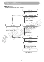
Страница 25: ...d Make settings for the light laser speaker brightness etc See page 36 Select a mode from Single Detection Multi Detection Select a scene from Dry Concrete Wet Concrete Partition Radar View Mark the locations of detected buried objects See page 26 See page 27 See page 28 See page 30 See page 34 See page 35 Using the Wall Scanner ...

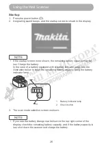
Страница 26: ...ase of a battery equipped with a battery indicator lamp see the illustration below to know the remaining battery capacity using the battery indicator lamp 1 Battery indicator lamp 2 Check button 2 1 3 The scan mode selection screen is shown NOTE If you see the battery change mark shown in the top right corner of the display check the remaining battery capacity and if the battery capacity is low sh...

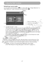
Страница 27: ...m which to detect any buried objects Scan results are shown in the scanner s display so that you can see the location and depth data of the buried object When there is a buried object under the sensor a burial detection mark blinks or a beep sounds to let you know of it 2 Multi Detection mode This mode performs three lines of buried object scan continuously The scan results for the three lines are...

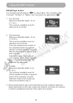
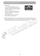
Страница 28: ...ely dried since placed and the concrete less than one year after the placement is referred to as wet concrete Select this scene in the case of wet concrete but to make it double sure it is recommended that Dry Concrete be also used 3 Partition Maximum detection depth 8 cm 3 1 8 This scene is suitable to scan for objects behind a wooden or gypsum board With no display of burial detection marks scan...

Страница 29: ...lock or brick With no display of burial detection marks scan results are shown in waveforms only See Searching for iron bars in a block fence in page 48 Some buried objects may not be detected up to the maximum detection depth depending on their size shape and material as well as the material condition and internal structure of the wall to be scanned ...

Страница 30: ...r slowly If moved too fast an error message is shown during which a scan is unavailable After detection do not release the scanner from the surface being scanned until marking is completed If released scan operation is discontinued During a scan if the scanner remains at rest for 10 seconds or more scan operation is discontinued When a scan is started from the right in front of a buried object sca...

Страница 31: ...31 3 Radar scan results are shown on the display Using the Wall Scanner ...

Страница 32: ... red in a yellow 8 Sensor area 9 Sensor s right edge line Represents the scanner s right edge 10 Burial detection mark Outside the sensor area A yellow 11 Operation guide arrow 12 Signaling sound on off 13 Battery change mark 14 Depth to the buried object 1 2 4 5 6 9 3 13 12 11 14 8 10 7 15 Area not yet scanned 16 Area already scanned 16 15 Multi Detection 1 Line 1 scan results 2 Line 2 scan resul...

Страница 33: ...ed object and the condition or internal structure of the wall to be scanned In that case estimate the correct location from the waveform in the image WARNING Before drilling sawing or routing into a wall protect yourself against hazards by using other information sources As the measuring results can be influenced through ambient conditions or the wall material there may be a hazard even though the...

Страница 34: ... 1 Move the scanner to where the burial detection mark on the screen is aligned with the sensor s center line 1 Sensor s center line 2 Make a marking at the recess at the center of the scanner s upper edge The mark represents the center of the buried object 2 Recess 1 2 Using the Wall Scanner ...

Страница 35: ...he sensor s right and left edge lines on the screen represent the scanner s both right and left edge lines 2 Make a marking at the recess on the scanner s right edge The mark represents the center of the buried object 1 Recess Shutdown Press and hold the power button The end screen is shown and after a few seconds the power is turned off NOTE Do not remove the battery until the end screen goes out...

Страница 36: ...are shown 4 Press the left button or right button to select your desired setting option The setting option that you selected is set 5 Press the apply button The screen reverts to the settings screen To exit the settings screen to go back to the previous screen press the settings button NOTE Setting changes are not reflected if the battery is removed when the settings screen is displayed Do not rem...

Страница 37: ...eration button is operated or when there is an object detected in the scanner s sensor area Off Low High High Bright Adjusts the brightness of the display backlight Low Middle High Middle Sleep Sets the period of time elapsed before the display backlight guide laser and light are turned off when the scanner is switched on and no operation takes place OFF 1 10 sec 20 sec 30 sec 60 sec 120 sec 240 s...

Страница 38: ...appropriate timing 14 4 V 18 V 18 V Unit Selects the unit of measure for the depth of buried objects cm inch Decimal inch Fractional cm Lang Selects the language used in the display English Deutsch Français Italiano Español Nederlands Português Русский English 1 Always turned on when OFF is selected 2 Not switched off automatically when OFF is selected Settings ...

Страница 39: ...1 Turn on the scanner If the scanner has already been switched on press the mode button 2 Select the scan mode of Single Detection and press the apply button 3 Select the scene of Dry Concrete and press the apply button NOTE To start scan operation wait for the operation guide arrow to be shown 1 2 Operation ...

Страница 40: ...nd left edge lines with your intended line to scan and apply the scanner to the concrete surface 5 Move the scanner slowly side to side 6 Scan results are shown on the display 7 Make markings at the detected iron bar locations See page 34 Operation ...

Страница 41: ...h can scan three lines be used 1 Resin pipe 2 Concrete 1 Place masking tape to the concrete surface to show scan lines in a square shape of 60 cm 23 5 8 1 Masking tape 2 Three lines to be scanned 3 Upper line 4 Middle line 5 Lower line 6 Operation start line A 30 cm 11 13 16 B 60 cm 23 5 8 1 6 B A 3 4 5 2 2 Turn on the scanner If the scanner has already been switched on press the mode button 1 2 O...

Страница 42: ...sensor s right and left edge lines with the upper masking tape line and slowly move the scanner on the line 6 Scan results are shown on the display The scan results of the upper line are shown in line 1 if the scanner is released from the concrete surface If the apply button is pressed the scan of line 1 is reverted so that you can start over a scan again Operation ...

Страница 43: ...igned with that of the upper line 8 Scan results are shown on the display The scan results of the middle line are shown in line 2 if the scanner is released from the concrete surface 9 Align the guide laser the sensor s right and left edge lines with the lower masking tape line and slowly move the scanner on the line NOTE Start scanning on the vertical masking tape line so that the starting positi...

Страница 44: ...e 11 You can recheck scan results and the locations of buried objects if the scanner is moved again from the position at which scan operation was started The screen three lines is scrolled in step with the movement of the scanner 1 1 The scan result screen is scrolled in the direction of the arrow if the scan ner is moved as shown at left NOTE When you check scan results apply the scanner to the s...

Страница 45: ... at the detected resin pipe locations A 30 cm 11 13 16 B 60 cm 23 5 8 It helps you identify the position of the buried object more easily if you scan also in the vertical direction with the scanner oriented perpendicularly A B A B ...

Страница 46: ... scanner has already been switched on press the mode button 2 Select the scan mode of Single Detection and press the apply button 3 Select the scan mode of Partition and press the apply button 4 Align the guide laser the sensor s right and left edge lines with your intended scan position and apply the scanner to the gypsum board 1 2 Operation ...

Страница 47: ...shown Light gauge steel graphics 4 Characteristically shown wooden pillar graphics 7 Make markings at the detected pillar locations NOTE Detection may be instable when the scanner has just been started up To stably detect buried objects wait for a while before you start scan operation Confirm scan results after several times of scan Depending on the detection environment or the material of objects...

Страница 48: ...n bars are placed between blocks and mortar is filled around each iron bar 1 Void 2 Mortar 3 Iron bar 4 Block 1 4 4 4 3 2 In this example use the scene of Radar View to be able to detect both iron bars and block voids 1 Turn on the scanner If the scanner has already been switched on press the mode button 2 Select the scan mode of Single Detection and press the apply button 1 2 Operation ...

Страница 49: ...49 3 Select the scan mode of Radar View and press the apply button 4 Move the scanner slowly side to side on the block fence s surface Operation ...

Страница 50: ...of iron bars through the characteristics and positions of the waveforms Iron bar Waveforms appear in deeper positions from the scan surface Block void Waveforms appear in shallower positions from the scan surface 1 Iron bar 2 Block void Characteristically shown iron bar graphics Characteristically shown block void graphics 1 2 Operation ...

Страница 51: ...o scan more accurately If masking tape or such is used on the scanning path it serves as a scanning aid for example by giving you a guide mark to help you move the scanner more accurately or giving a guide mark when you make markings for the estimated locations of buried objects The illumination of the guide laser helps you scan correctly by giving you a guide mark to move the scanner straight 1 M...

Страница 52: ...eing scanned 2 Upper surface of an iron bar 3 Black band A 9 2 cm 3 5 8 Burial detection marks may appear in misaligned positions due to the effects of concrete honeycombs or other irregularities in concrete In that case estimate the correct location from the waveform in the image In the image as shown in the right example point a is the correct location When a yellow marker does not appear as wel...

Страница 53: ...ingle objects Detected as independent two pieces Detected as one piece NOTE In the case of the selection of an excavation or boring place allow the scan starting position to have a good distance from the detected place Scan direction The detection accuracy is the highest when the buried object and the scanner are positioned in parallel Operation ...

Страница 54: ...sitioned in parallel When how iron bars are placed in concrete is unknown scan in more than one direction The correct detection may be prevented when the buried object is right in front of the scanner and in parallel to the scan direction In that case scan at more than one position Operation ...

Страница 55: ...e error sudden change When the scanner has a sudden temperature change during which the correct scan is prevented the message shown at right appears and the scanner is forced to turn off Turn on the power under a temperature environment within the scanner s specification Internal error When the scanner detects an internal processing error during which the correct scan is prevented the message show...

Страница 56: ... Speed excess protection function When your operation is too fast during which the correct scan is prevented the message shown at right appears and prompts you to correct your operation Protection System ...

Страница 57: ...ted neutral detergent NOTE Never wash the product with water The entrance of water inside the product may cause a malfunction Never use gasoline benzine thinner alcohol or the like Discoloration deformation or cracks may result To maintain product SAFETY and RELIABILITY repairs any other maintenance or adjustment should be performed by Makita Authorized or Factory Service Centers always using Maki...

Страница 58: ...t signature sur la dernière page DEUTSCH EU Konformitätserklärung Wir als die Hersteller Makita Europe N V Geschäftsadresse Jan Baptist Vinkstraat 2 3070 Kortenberg Belgien beauftragen Hiroshi Tsujimura mit der Zusammenstellung der technischen Dokumentation und erklären unter unserer alleinigen Verantwortung dass das die Produkt e Bezeichnung Akku Ortungsgerät Bezeichnung des der Typs Typen DWD181...

Страница 59: ...rtenberg Bélgica Persona responsable Hiroshi Tsujimura Director Makita Europe N V fecha y firma en la última página PORTUGUÊS Declaração de conformidade da UE A empresa na qualidade de fabricante Makita Europe N V Endereço comercial Jan Baptist Vinkstraat 2 3070 Kortenberg Bélgica Autorizamos Hiroshi Tsujimura a realizar a compilação do ficheiro técnico e declaramos ao abrigo da nossa própria resp...

Страница 60: ...etildiğini beyan ediyoruz Beyan yeri Kortenberg Belçika Sorumlu kişi Hiroshi Tsujimura Müdür Makita Europe N V tarih ve imza son sayfada bulunmaktadır SVENSKA EU försäkran om överensstämmelse I egenskap av tillverkare Makita Europe N V med företagsadress Jan Baptist Vinkstraat 2 3070 Kortenberg Belgien auktoriserar vi Hiroshi Tsujimura för sammanställningen av den tekniska dokumentationen och förs...

Страница 61: ...došanas vieta Kortenberg Beļģija Atbildīgā persona Makita Europe N V direktors Hiroshi Tsujimura datumu un parakstu skatiet pēdējā lapā LIETUVIŲ KALBA ES atitikties deklaracija Mes gamintojai Makita Europe N V įmonės adresas Jan Baptist Vinkstraat 2 3070 Kortenberg Belgija įgaliojame Hiroshi Tsujimura parengti techninę bylą ir savo išskirtine atsakomybe deklaruojame kad gaminys iai žymuo Įkraunama...

Страница 62: ...C63000 2018 A nyilatkozattétel helye Kortenberg Belgium Felelős személy Hiroshi Tsujimura igazgató Makita Europe N V dátum és aláírás az utolsó lapon SLOVENSKY Vyhlásenie o zhode v rámci EÚ Naša spoločnosť ako výrobca Makita Europe N V firemná adresa Jan Baptist Vinkstraat 2 3070 Kortenberg Belgicko Týmto oprávňujeme Hiroshi Tsujimura na zostavenie technického súboru a vyhlasujeme na našu výhradnú...

Страница 63: ...ersoni përgjegjës Hiroshi Tsujimura drejtor Makita Europe N V data dhe firma në faqen e fundit БЪЛГАРСКИ EС декларация за съответствие В качеството си на производител ние Makita Europe N V с адрес на управление Jan Baptist Vinkstraat 2 3070 Kortenberg Белгия упълномощаваме Hiroshi Tsujimura да състави техническото досие и да декларира от наше име че продукта ите Наименование Акумулаторен стенен ск...

Страница 64: ... declaraţiei Kortenberg Belgia Persoana responsabilă Hiroshi Tsujimura Director Makita Europe N V data şi semnătura pe ultima pagină СРПСКИ EУ декларација о усаглашености Ми као произвођач Makita Europe N V пословна адреса Jan Baptist Vinkstraat 2 3070 Kortenberg Белгија овлашћујемо Hiroshi Tsujimura да састави техничку документацију и под нашом искључивом одговорношћу изјави да следећи производ о...

Страница 65: ...ція на відповідність вимогам ЄС згідно 2014 53 EU Нотифікований орган TÜV SÜD Product Service GmbH Zertifizierstellen Ridlerstraße 65 80339 MÜNCHEN Німеччина Ідентифікаційний номер 0123 номера сертифікатів TPS RED500184 i01 та виготовлені згідно таких єдиних стандартів EN 61010 1 2010 EN 60825 1 2014 EN 62311 2008 EN 301 489 1 V2 1 1 2017 02 EN 301 489 33 V2 2 1 2019 04 EN 302 066 V2 1 1 2017 01 E...

Страница 66: ...12 3032 as amended Type examination for S I 2017 1206 Approved Body TUV SUD BABT UNLIMITED Octagon House Concorde Way Segensworth North Fareham Hampshire PO15 5RL United Kingdom Identification number 0168 Certificate number UK RER001840 i01 and are manufactured in accordance with the following Designated Standards EN 61010 1 2010 EN 60825 1 2014 EN 62311 2008 EN 301 489 1 V2 1 1 2017 02 EN 301 489...

Страница 67: ...07 07 2021 Makita Europe N V Jan Baptist Vinkstraat 2 3070 Kortenberg Belgium ...

Страница 68: ...www makita com Makita Europe N V Jan Baptist Vinkstraat 2 3070 Kortenberg Belgium Makita Corporation 3 11 8 Sumiyoshi cho Anjo Aichi 446 8502 Japan ...

Отзывы: