© 2017 Sensata Technologies
13
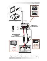
Figure 2-5, MMS1012-G Model Dimensions
~
16
"
(16.59")
~ 6 " (6.71")
10"
~ 5 "
(5.125")
~ 5"
Mounting holes x4
[
¼” (0.25") diameter
]
~ 7 " (7.51")
~ 8 " (8.41")
5
8
5
8
1
8
7
16
1
2
3
4
~
4
"
(4.625")
• If installing in a recreational vehicle, do not attempt to use the
vehicle’s metal frame in place of the negative connection or DC
ground. The inverter requires a reliable negative and ground
return path directly to the battery.
• DC wires and cables should be tied together with wire ties or
electrical tape approximately every 6 inches (15.2 cm). This
helps improve the surge capability and reduces the effects of
inductance, which improves the inverter waveform and reduces
wear on the inverter’s
fi
lter capacitors.
• Use only copper wires with a minimum temperature rating of
75°C (167°F).
• To ensure maximum performance from the inverter, minimize
all connections from the battery bank to the inverter
Exception:
the DC overcurrent disconnect in the positive line.
Installation


