15
58-601 Pulsar
®
Radar Transmitter
2.4.2.2 Initial Installation
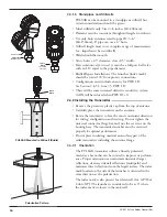
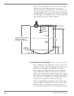
Ideally, the transmitter should be mounted half the radius
from the tank wall. Align the index mark so it is at an angle
of 45 degrees to a line from the radar unit to the nearest
tank wall. For horizontal cylindrical vessels, align the
launcher (index mark) so it is facing along the long axis of
the vessel. Do not optimize the Quality (signal strength) at
one level in the vessel. Once properly oriented, tighten set
screws and Universal connector (30 ft-lbs of force).
A transmitter mounted within 18" (45 cm) of a tank wall
may demand orientation adjustments to limit multipath
and optimize performance. See Section 2.4.2.3 Signal Loss.
NOTE: ALWAYS RUN THE TARGET REJECTION ROUTINE AFTER
MAKING CHANGES TO MENU CHOICES (
Antenna Type
,
Antenna Mount, Sensor Offset, Tank Height, Blocking
Distance, Dielectric, Turbulence, Rate Change, Foam
) or
when launcher is repositioned.
2.4.2.3 Poor Signal Quality
Poor signal quality has many potential causes. Following are
two initial areas for investigation.
Launcher Orientation:
Initial launcher orientation is always
45 degrees (see Sections 2.4.1 & 2.4.2). In tall vessels and
when antenna is mounted close to the tank wall, improve-
ment in signal quality may be attained by rotating the
launcher to 90 degrees.
Signal Loss:
If the Level signal is lost repeatedly at a specific
point in the vessel, it is usually a symptom that multipath
(side-wall reflections) are causing cancellation by returning
to the transmitter exactly 180° out of phase with the Level
signal. Utilize the following procedure:
• Go to transmitter screen #4 which shows both Level and
signal Quality.
• Bring the Level up (or down) to the exact point where the
signal is repeatedly lost. Monitor the Quality value as this
point is being approached. The Quality value will degrade
to a low point before it begins to increase.
• At the point of poorest Quality, loosen both the Universal
connector and the set screw. Slowly rotate the launcher
clockwise approximately 10–20° (the transmitter can be
rotated independently). Allow the unit to stabilize for
approximately 1 minute. Repeat this process until the signal
Quality value is optimized.
• Without disturbing the position of the launcher, position
the transmitter head back to its most convenient location.
• Tighten both the Universal connector (30 ft-lbs of force) and
Launcher set screw.
1/2 Radius
Launcher
Index
mark
(facing
45
°
)
45
°
90
°
Top View
Mounted
1
⁄
2
radius
Set Screw
Universal
Connector
Содержание pulsar RX5
Страница 1: ...Pulse Burst Radar Level Transmitter Model RX5 RX5 software v2 1a Installation and Operating Manual ...
Страница 33: ...33 58 601 Pulsar Radar Transmitter 3 4 1 Agency FM CSA Drawing and Entity Parameters ...
Страница 46: ...58 601 Pulsar Radar Transmitter Notes ...
Страница 47: ...58 601 Pulsar Radar Transmitter Notes ...


