23
58-601 Pulsar
®
Radar Transmitter
Display
Action
Comment
23
Set 20mA
xxx.x units
Enter
the value for the
20 mA
point
During normal operation, mA value will never read into the
area defined by the
Blocking Distance
value. Refer to #14.
24
Damping
xx
Enter
the
Damping
factor
A damping factor (0–45) may be added to smooth a noisy
display and/or output due to turbulence.
25
SysFault
(select)
Select
the system
Fault
value
Select
3.6 mA
,
22 mA
or
HOLD
(last value). See Section
3.3.2 for Fault information.
26
LOEFault
(select)
Select
the
Loss of Echo Fault
value
Select
3.6 mA
,
22 mA
or
HOLD
(last value).
27
LOEDelay
(xxx sec)
Enter
value for Loss of Echo Delay
Select a value 0–255; 30 is default
28
SZ Fault
(select)
Select
the
Safety Zone Fault
Safety Zone
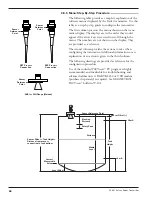
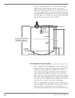
is a user-defined area just below the
Blocking
Distance
. See drawing on page 20. Enable Fault if neces-
sary to ensure safe, reliable high-level readings in critical
applications. Choices are
None, 3.6 mA
,
22 mA
,
Latch
3.6
or
Latch 22
. If
Latch 3.6
or
Latch 22
is chosen, the
loop current will remain in alarm until it is manually
cleared with the SZ Alarm Reset below (#30)
29
SZHeight
(xx.x units)
Enter
a
Safety Zone Height
Enter a distance value that develops a safety zone just
below the
Blocking Distance
. Here the unit will report a
Safety Zone Fault
(#28) if the level rises into this area.
30
SZ Alarm
Reset
Reset
Safety Zone Latch
Clear a latched
Safety Zone
alarm.
31
Poll Adr
(xx)
Enter
HART
Poll Address
number
Enter a HART
Poll Address
(0–15). Enter 0 for a single
transmitter installation; enter 1–15 for multi-drop network
(loop will latch at 4 mA).
32
Trim 4
Fine tune
the 4 mA point
Attach a mA meter to the output. If the output does not
equal 4.00 mA, adjust the value on the display until meter
reads 4.00 mA.
33
Trim 20
Fine tune
the 20 mA point
Attach a mA meter to the output. If the output does not
equal 20.00 mA, adjust the value on the display until
meter reads 20.00 mA.
34
Trim Lvl
xxx.x units
Fine Tune
the
Level
value
Trim Lvl
is an offset value (± 10" or 244mm) to be used
to force the transmitter to output the exact Level. This
should only be used after all parameters have been
entered correctly,
Tank Height
and
Sensor Offset
have
been confirmed accurate and it has been confirmed that
the transmitter is tracking the correct level target.
35
PIPE ID
xx.x units
Enter
Pipe ID
For mounting in a standpipe/stillwell. Enter a value for
inside diameter of the pipe. Range of values is 0", 3" to
20" (0, 40 to 500 mm).
Value MUST be left as 0 if no
standpipe/stillwell is present.
36
Loop Tst
xx.xx mA
Enter
a mA Output value
Enter a mA Output of any given value to perform loop test.
37
New Pass
xxx
Enter
new
Password
Use arrows to select desired value between 0 and 255;
0=No Password. During normal operation, an encrypted
password is shown.
38
Status
Review
Status
information
Status
information is updated continuously showing only
the most recent diagnostic events. See
Diagnostic
screen
in Factory Menu for a cumulative review.
39
Language
Select
Language
Select the
Language
that will be displayed on the trans-
mitter screen. Choices are English (default), Spanish,
German and French.
40
ModelRX5
Verxx.xx
Revision information
Processor firmware Rev level
Coprocessor firmware Rev level
Содержание pulsar RX5
Страница 1: ...Pulse Burst Radar Level Transmitter Model RX5 RX5 software v2 1a Installation and Operating Manual ...
Страница 33: ...33 58 601 Pulsar Radar Transmitter 3 4 1 Agency FM CSA Drawing and Entity Parameters ...
Страница 46: ...58 601 Pulsar Radar Transmitter Notes ...
Страница 47: ...58 601 Pulsar Radar Transmitter Notes ...


