12
58-601 Pulsar
®
Radar Transmitter
2.4 Mounting
The PULSAR Radar transmitter can be mounted to a vessel
using a variety of process connections. Generally, either a
threaded or flanged connection is used.
2.4.1 Installing the Antenna
Before installing, make sure:
• Model and Serial numbers on the nameplates of the PULSAR
antenna and transmitter are identical.
• Process temperature, pressure, dielectric, turbulence and
distance are within the antenna specifications for the
installation.
• Rod of a Dielectric Rod antenna is protected from bending
or breaking; there is no metal sub-structure.
• Insulating material is not placed around any part of the
Radar transmitter including the antenna flange.
• Protective cap is kept on the antenna if the transmitter is to
be installed at a later time.
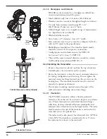
• Antenna is being mounted in the optimal location. See fol-
lowing sections: Location, Beam Angle, Obstructions and
Nozzles for specific information.
• If the liquid level is allowed onto the antenna, noise and
media buildup drastically decrease reliable measurement.
Liquid should not be allowed closer than 2 inches (50 mm)
from the bottom of the antenna.
2.4.1.1 Location
Ideally, the Radar transmitter should be mounted providing
an unobstructed signal path to the liquid surface where it
should illuminate (with microwave energy) the largest,
possible surface area. See Section 2.4.1.2, Beam Angle.
Unavoidable obstacles will produce reflections that must be
minimized during field configuration. See Section 2.6.5.1,
Target Rejection. Mount in a location equal to
1
⁄
2
the radius
of tank top. Do not mount in center of vessel nor closer
than 18" (45 cm) of tank wall.
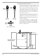
2.4.1.2 Beam Angle
The various antenna designs exhibit different beam patterns.
Ideally, the beam pattern should illuminate the maximum
liquid surface with a minimum striking other objects in the
vessel including the tank wall. Use these drawings to deter-
mine the optimum installation location.
1/2
Radius
> 18"
(45 cm)
D
W
W
∝
∝
Beam Spread, W @-3dB; ft (m)
Antenna
Beam Angle
(
∝
)
Dielectric Rod
25°
4" Horn
25°
6" Horn
17°
Distance, D
10 (3)
4.5 (1.37)
4.5 (1.37)
3.0 (0.91)
20 (6)
8.9 (2.71)
8.9 (2.71)
6.0 (1.83)
30 (9)
13.3 (4.05)
13.3 (4.05)
9.0 (2.74)
40 (12)
17.8 (5.43)
17.8 (5.43)
12.0 (3.66)
50 (15)
22.2 (6.77)
22.2 (6.77)
15.0 (4.57)
60 (18)
26.6 (8.11)
26.6 (8.11)
18.0 (5.49)
65 (20)
28.9 (8.81)
28.9 (8.81)
19.5 (5.95)
Содержание pulsar RX5
Страница 1: ...Pulse Burst Radar Level Transmitter Model RX5 RX5 software v2 1a Installation and Operating Manual ...
Страница 33: ...33 58 601 Pulsar Radar Transmitter 3 4 1 Agency FM CSA Drawing and Entity Parameters ...
Страница 46: ...58 601 Pulsar Radar Transmitter Notes ...
Страница 47: ...58 601 Pulsar Radar Transmitter Notes ...


