11
58-601 Pulsar
®
Radar Transmitter
2.3.3.1
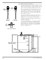
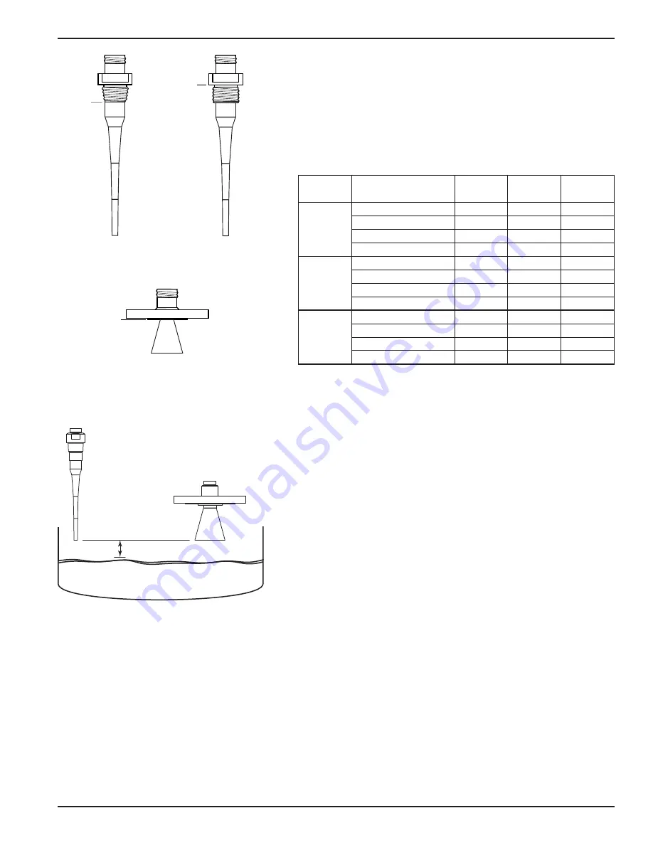
The chart below shows the maximum measuring range
(Distance) of each antenna based on fundamental condi-
tions of Dielectric, Distance and Turbulence. Maximum
distance is calculated as Tank Sensor Offset
(see page 20). It is measured from the Sensor Reference
Point (bottom of NPT thread, top of BSP thread or face
of a flange).
2.3.3.2 Minimum Distance
If the liquid level is allowed onto the antenna, noise and
media build-up drastically decrease reliable measurement.
Liquid should not be allowed closer than 2 inches (50 mm)
from the bottom of the antenna.
2.3.3.3 Problematic Applications; GWR Alternative
Some application concerns can be problematic for Radar.
For these, Guided Wave Radar is recommended:
• Extremely low dielectric media (
ε
r
<2.0)
• Stillwells, standpipes, bridles, cages and bypass columns.
• Very weak reflections from the liquid surface, particularly
during turbulence, can cause poor performance.
• Tanks heavily cluttered with false targets (mixers, pumps,
ladders, pipes, etc.)
• During times of very low liquid levels of low dielectric media,
the metal tank bottom may be detected deteriorating per-
formance.
• Foam can either absorb or reflect the microwave energy
depending upon the depth, dielectric, density and wall
thickness of the bubbles. Due to typical variations in the
amount (depth) of foam, it is impossible to quantify per-
formance. It may be possible to receive most, some or none
of the transmitted energy.
• Extremely high liquid levels (Overflow) conditions when
liquid very near the antenna can cause erroneous readings
and measurement failure.
Dielectric
Turbulence
Dielectric
Rod (1
1
⁄
2
")
4" Horn
6" Horn
1.7-3.0
None
35 (10.7)
40 (12.2
45 (13.7)
Light, < 0.5"
28 (8.5)
33 (10.1)
37 (11.3)
Moderate, < 1.0"
21 (6.4)
26 (7.9)
29 (8.8)
Heavy, > 1.0"
15 (4.6)
17 (5.2)
20 (6.1)
3.0-10.0
None
50 (15.2)
55 (16.8)
60 (18.3)
Light, < 0.5"
40 (12.2
44 (13.4)
48 (14.6)
Moderate, < 1.0"
30 (9.1)
33 (10.1)
35 (10.7)
Heavy, > 1.0"
20 (6.1)
22 (6.7)
25 (7.6)
10.0-100
None
65 (20)
65 (20)
65 (20)
Light, < 0.5"
52 (15.8)
52 (15.8
53 (16.2)
Moderate, < 1.0"
39 (11.9)
39 (11.9)
41 (12.5)
Heavy, > 1.0"
25 (7.6)
27 (8.2)
30 (9.1)
MAXIMUM DISTANCE
feet (meters)
2" (50 mm)
Sensor
Reference
Point
Sensor
Reference
Point
Sensor
Reference
Point
NPT Process
Connection
BSP Process
Connection
ANSI or DIN Welded Flange
Refer to Eclipse
®
bulletin 57-101
Dielectric rod minimum dielectric = 2.0
Содержание pulsar RX5
Страница 1: ...Pulse Burst Radar Level Transmitter Model RX5 RX5 software v2 1a Installation and Operating Manual ...
Страница 33: ...33 58 601 Pulsar Radar Transmitter 3 4 1 Agency FM CSA Drawing and Entity Parameters ...
Страница 46: ...58 601 Pulsar Radar Transmitter Notes ...
Страница 47: ...58 601 Pulsar Radar Transmitter Notes ...


