background image

IT

EN

FR

ES

13

Madas Technical Manual

 - 4|4.1b - REV. 0 of 10

th

 May 2018

RG/2M

  4.1 - RECOMMENDED PERIODIC CHECKS

• Use a suitable calibrated tool to ensure the bolts are tightened as indicated in 3.2;
• Check the tightness of the flanged/threaded connections on the system;
• Check the tightness and operation of the regulator;

The final user or installer is responsible for defining the frequency of these checks based on the extent of the service conditions.

  4.2 - ADJUSTING THE OUTLET PRESSURE

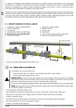
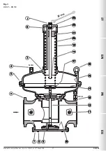
Before starting the system, make sure that the spring supplied with the regulator is suitable for the desired adjustment 

pressure. The P2 output pressure (unless specifically requested) is factory set at approximately the minimum calibration value. 
Adjust the outlet pressure as follows:

•  Set the adjustment screw (

1

) at minimum calibration;

•  Start the system or make sure there is a minimum flow downstream of the regulator;
•  To increase the pressure calibration downstream of the regulator, tighten the adjustment screw (

1

) to the desired value. Perform 

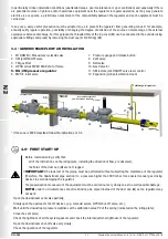
the reading with a calibrated pressure gauge, installed downstream of the regulator to at least 5 DN (see example in 3.4);

•  Use pressure outlets (

11

) on the device only for zero flow or very low flow measurements. 

  4.3 - REPLACING THE SPRING

The step must be carried out without gas inside the regulator.

•  IMPORTANT:


Springs that are: Grey, Red, Brown use the upper spring guide (

21

) code RP-0150/SX


Spring colours: Yellow, Black use the upper spring guide (

21

) code RP-0155/SX

Replace the spring as follows:
•  Completely loosen the adjustment screw (

1

) to the stroke end;

•  Unscrew the cap (

22

) from the pipe (

19

);

•  Remove the spring (

20

) from inside the pipe (

19

);

•  If necessary (check spring colour), the upper spring guide (

21

) must be replaced as follows: 

•  Remove the pin (

18

); 

•  Keeping the cap (

22

) blocked, turn the fastening screw (

1

) clockwise until the spring guide (

21

) is released from 

the guide pin (

2

);  

•  Remove the spring guide (

21

) completely by turning it clockwise; 

•  Fit the new spring guide at the end of the threaded bar (

23

); 

•  Turn the new spring guide anticlockwise in order to secure the threaded bar (

23

), until it is coupled with the pin (

2

); 

•  Keeping the cap (

22

) blocked in place, turn the adjustment screw (

1

) anticlockwise until the spring guide is at the 

opposite end of the threaded bar (

23

); 

•  Reassemble the pin (

18

).

•  Insert the new adjustment spring, making sure to position it correctly inside the lower spring guide (

17

).

•  Screw the cap (

22

) to the pipe (

19

).

•  Adjust the output pressure as indicated in 4.2.

Содержание RG/2M

Страница 1: ...0 of 10th Oct 2018 RG 2M MADE IN ITALY II 2G II 2D I T E N F R E S Pressione massima di esercizio Maximum operating pressure Pression maximum de fonctionnement Presi n m xima de funcionamiento 0 5 bar...

Страница 2: ...sioni tabella 1 28 Dimensions table 1 Dimensions tableau 1 Dimensiones tabla 1 Caratteristiche molle di regolazione tabella 2 29 Regulation spring data table 2 Caracteristiques des ressorts de reglage...

Страница 3: ...11 1 2 LEGENDA SIMBOLI ATTENZIONE Viene richiamata l attenzione su dettagli tecnici rivolti al personale qualificato PERICOLO In caso di inosservanza oltre a danni a beni materiali possono essere proc...

Страница 4: ...corpo a inutili sforzi meccanici calcolare inoltre lo spazio per l inserimento della guarnizione di tenuta Per le fasi di serraggio necessario munirsi di una o pi chiavi dinamometriche tarate od altr...

Страница 5: ...positivo vedi foto a lato In caso sia prevista l installazione dell apparecchio in una rampa cura dell installatore prevedere adeguati supporti o appoggi correttamente dimensionati per sostenere e fis...

Страница 6: ...cettazione a monte es elettrovalvole valvola di blocco OPSO ecc Attendere che la pressione a valle si stabilizzi al valore di taratura P2 della molla indicato in targhetta Chiudere il rubinetto di sfi...

Страница 7: ...azioni a portata zero o a portata molto ridotta 4 3 SOSTITUZIONE DELLA MOLLA L operazione deve essere effettuata senza la presenza di gas all interno del regolatore IMPORTANTE Le molle colore Grigio R...

Страница 8: ...nel paese in cui si esegue tale operazione 7 0 GARANZIA Valgono le condizioni di garanzia stabilite col fabbricante al momento della fornitura Per danni causati da Uso improprio del dispositivo Inosse...

Страница 9: ...industrial use in industrial sites Reference standards EN 88 1 EN 13611 1 2 KEY OF SYMBOLS ATTENTION Attention is drawn to the technical details intended for qualified staff DANGER Inobservance may ca...

Страница 10: ...nges are perfectly coaxial and parallel in order to prevent unnecessary mechanical stress to the body Also calculate the space to insert the seal gasket With regard to tightening operations equip your...

Страница 11: ...oto on the side If the device needs to be installed in a ramp it is the installer s responsibility to provide suitable supports or correctly sized supports to properly hold and secure the assembly Nev...

Страница 12: ...olenoid valves OPSO shut off valve etc Wait until the downstream pressure stabilises at the calibration value P2 of the spring indicated on the rating plate Close the vent valve Check the tightness of...

Страница 13: ...in 3 4 Use pressure outlets 11 on the device only for zero flow or very low flow measurements 4 3 REPLACING THE SPRING The step must be carried out without gas inside the regulator IMPORTANT Springs...

Страница 14: ...operation is performed 7 0 WARRANTY The warranty conditions agreed with the manufacturer at the time of the supply apply Damage caused by Improper use of the device Failure to observe the requirements...

Страница 15: ...13611 1 2 L GENDE DES SYMBOLES ATTENTION Nous attirons votre attention sur les d tails techniques s adressant au personnel qualifi DANGER En cas de non respect outre des dommages mat riels il existe u...

Страница 16: ...tre le corps des efforts m caniques inutiles calculer en outre l espace pour l insertion du joint d tanch it Pour les phases de serrage il faut se munir d une ou de plusieurs cl s dynamom triques cali...

Страница 17: ...r le c t Si l installation de l appareil est pr vue dans une rampe il incombe l installateur de pr voir des supports ad quats ou des appuis correctement dimensionn s pour soutenir et fixer l ensemble...

Страница 18: ...ovannes vanne de fermeture OPSO etc Attendre que la pression en aval se stabilise la valeur d talonnage P2 du ressort indiqu e sur la plaque Fermer le robinet d vacuation Contr ler l tanch it de tous...

Страница 19: ...eil que pour effectuer des mesures d bit nul ou tr s faible 4 3 REMPLACEMENT DU RESSORT L op ration doit tre effectu e sans la pr sence de gaz autour du r gulateur IMPORTANT Les ressorts couleur Gris...

Страница 20: ...s le pays o cette op ration est effectu e 7 0 GARANTIE Les conditions de garantie qui s appliquent sont celles qui sont tablies avec le fabricant lors de la livraison Pour des dommages caus s par Un u...

Страница 21: ...n sitios industriales Normas de referencia EN 88 1 EN 13611 1 2 LEYENDA DE S MBOLOS ATENCI N Se llama la atenci n sobre detalles t cnicos dirigidos al personal cualificado PRECAUCI N En caso de incump...

Страница 22: ...te coaxiales y paralelas para evitar someter el cuerpo a esfuerzos mec nicos in tiles adem s calcule el espacio para introducir la junta de estanqueidad Para las fases de apriete es necesario procurar...

Страница 23: ...ostado Si se ha previsto la instalaci n del aparato en una rampa es deber del instalador preparar soportes o apoyos adecuados correctamente dimensionados para sostener y fijar el conjunto Nunca deje p...

Страница 24: ...riores por ej electrov lvulas v lvula de bloqueo OPSO etc Espere a que la presi n posterior se estabilice en el valor de calibrado P2 del muelle indicado en la placa Cierre el grifo de alivio Controle...

Страница 25: ...de presi n 11 en el aparato solo para mediciones con caudal cero o con caudal muy reducido 4 3 SUSTITUCI N DEL MUELLE La operaci n debe efectuarse sin la presencia de gas en el interior del regulador...

Страница 26: ...el que se realiza esta operaci n 7 0 GARANT A Valen las condiciones de la garant a establecidas con el fabricante en el momento del suministro Por da os causados por el uso impropio del dispositivo el...

Страница 27: ...IT EN FR ES 27 Madas Technical Manual 4 4 1b REV 0 of 10th May 2018 RG 2M fig 1 DN 125 DN 150 30 mm G 3 4 G 3 8...

Страница 28: ...io superiore 4 Tappo antipolvere 5 Viti di fissaggio coperchio superiore 6 Corpo 7 Fondello 8 Viti di fissaggio fondello 9 Otturatore 10 Rondella di tenuta 11 Presa di pressione 12 Perno centrale 13 P...

Страница 29: ...50 13x100x460x17 5 MO 8600 VG giallo yellow jaune amarillo 230 350 15x100x460x17 5 MO 8700 VN nero black noir negro 300 450 it numero di spire totali it total number of turns it nombre total de spires...

Страница 30: ...W apr s les chiffres indiquant les connexions pour obtenir rondelle de tenue membrane de compensation et membrane de fonctionnement en FKM A adir la letra V a continuaci n de las cifras que indican l...

Страница 31: ...ccords brides Conexiones embridadas Attacchi Connections Raccords Conexiones P2 mbar Regolatore Regulator Regulateur Regulador Codice Code Code C dice DN 125 15 30 RX11 010 30 150 RX11 020 100 250 RX1...

Страница 32: ...ons le droit de toute modification technique et constructive Nos reservamos el derecho de realizar cualquier cambio t cnico y estructural Sede legale Via V Moratello 5 6 7 37045 Z A I Legnago VR Italy...

Отзывы: