ES
FR
EN
IT
12
Madas Technical Manual
- 4|4.1b - REV. 0 of 10
th
May 2018
RG/2M
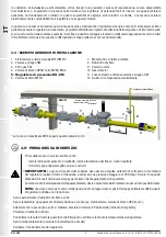
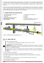
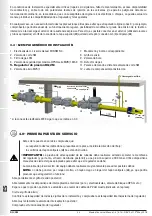
3.4 - GENERIC EXAMPLE OF AN INSTALLATION
1. M16/RM N.C. Manual reset solenoid valve
2. SM jerk ON/OFF valve
3. FM gas filter
4. OPSO series MVB/1 MAX shut off valve
5. RG/2M pressure regulator
6. MVS/1 relief valve
7. Pressure gauge and relative button
8. Vent valve
9. Ball valve
10. Gas detector
11. SM remote jerk ON/OFF valve lever control
12. Expansion joint/anti-vibration mount
4.0 - FIRST START-UP
Before commissioning, verify that:
• all of the instructions on the rating plate, including the direction of flow, are observed;
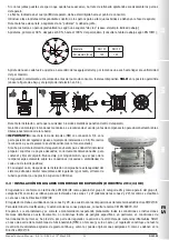
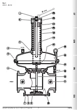
• the holes of the dust cap (
4
) are not clogged.
• IMPORTANT:
The leak test of the piping must be performed without subjecting the membrane of the regulator
(therefore, the downstream pipe section) to a pressure higher than 300 mbar. Use special manual gas closing
devices to avoid damaging the regulator;
• The pressurisation manoeuvre of the equipment must be carried out very slowly so as to avoid possible damage.
NOTE:
under no circumstances should a blind cap be placed instead of the dust cap (
4
) as the regulator may
not work;
• Open the downstream vent valve partially;
• Slowly open the upstream shut-off devices (e.g. solenoid valves, OPSO shut-off valve, etc.);
• Wait until the downstream pressure stabilises at the calibration value P2 of the spring (indicated on the rating plate);
• Close the vent valve;
• Check the tightness of all the system gaskets and check the internal/external tightness of the regulator;
• Open the downstream shut-off valve very slowly;
• Check the operation of the regulator.
In particularly critical installation conditions (unattended areas, poor maintenance or poor ventilation) and especially if there
are potential sources of ignition and/or hazardous equipment near the regulator in regular operation, as they may generate
electric arcs or sparks, a preliminary assessment of the compatibility between the regulator and such equipment must be
carried out.
In any case, every useful precaution must be adopted so as to prevent the regulator from generating zones 0: for example,
annually verify regular operation, possibility of changing the degree of emission of the source or intervening on the external
explosive substance discharge. For this purpose the threaded hole of the top cover (
3
) can be connected to the outside (using
appropriate fittings and pipes) by removing the dust cap (G 3/4 fitting) (
4
).
1
2
3
4
5
6
8
9
7
7
10
11
piping
application
discharge in open air
internal thermal unit
non-hazardous ventilated zone*
external roof
12
5 DN
* if the zone is ATEX classified follow the indications of 3.3


