background image

84   

SeCtion b

   SoFtware Manual

RetuRn to toC

MaCe HydRoMaCe 3000

   Product Manual              

85

RetuRn to toC

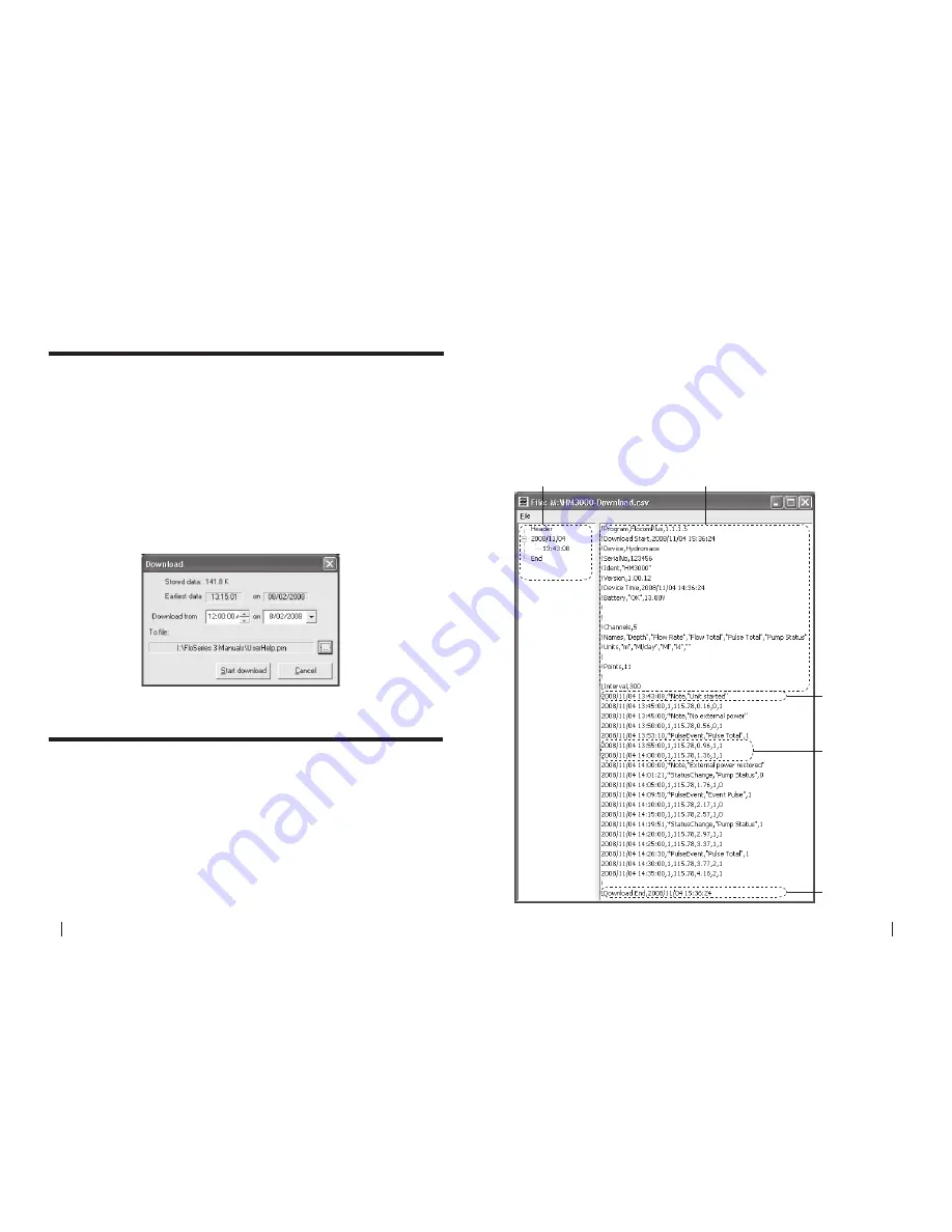
28.0  Downloading stored data

From the Start up screen click 

“Connect >Direct”

 to display the main menu.

Select 

“Download” 

to initiate the stored data download procedure. 

A save file dialogue box will appear.  The default file name is the unit ID.  The 

default target directory is the directory into which the previous download file 

was stored.
Click 

“OK”

 once you are ready to download the device.  The 

“download” 

dialogue box will appear which shows the amount of stored data in the 

device and the date of the earliest available record. If the download end time 

is left unchanged or set to a time earlier than the earliest record, all stored 

records will be downloaded. Otherwise, only those data stored after the 

chosen “Download from” date will be downloaded.
Click 

“Start download” 

to complete the download procedure.

29.0  View downloaded data file

This function is accessed via the 

“File”

 menu and then selecting the 

“View 

download file”

 option. The 

“File”

 menu is only available when not connected 

to the HM3000.

Opening a file

On entry, an open file prompt window is displayed. If downloaded data was 

saved during the current session, the last downloaded data file appears as 

the default selection. On selecting 

“Open”

 the selected file is loaded and if 

successful the data is displayed as a text file. A different downloaded data 

file may be selected at any time by selecting the local 

“File”

 function and 

repeating the file selection procedure. 

Viewing a file

Time stamp tree view

This pane enables the user to quickly navigate the data file by date and 

time. Expand the tree on the date of interest by clicking the “

+

” to reveal the 

various time stamps. Click the time stamp you wish to view and the data file 

will automatically scroll to it.

Header information

Time stamp tree view

Status messages

Time stamped data

End of file

ChaNgeD

Содержание HydroMace 3000

Страница 1: ...P R O D U C T M A N U A L www macemeters com ...

Страница 2: ...ents No part of this publication may be reproduced stored in a retrieval system or transmitted in any form or any means electronic or mechanical including photocopying and recording for any purpose other than the purchaser s personal use without the written permission of Measuring Control Equipment P L Copyright 1996 2009 MACE P L All rights reserved Part No 825 319 Rev 1 4 Code 080209 40 years of...

Страница 3: ...ts 15 9 0 Wiring analogue inputs 16 10 0 Wiring digital outputs 18 11 0 Wiring analogue outputs 18 12 0 Installing additional cards 19 13 0 Installing a Series3 FloSI card 20 14 0 Maintenance 21 14 1 Battery maintenance 21 14 2 Solar panel maintenance 21 14 3 Sensor maintenance 22 14 4 Depth sensor reference filter maintenance 22 Section A Hardware Manual Chapter Page This is an interactive PDF Th...

Страница 4: ...ents 88 Section B Software Manual Chapter Page 15 0 Introduction to FloCom 25 16 0 Installing the software 26 17 0 Connecting to the device 28 17 1 Connecting to the device using the serial port 28 17 2 What to do if the password is lost forgotten 29 18 0 System information 30 19 0 HM3000 settings dialogue box 32 19 1 General settings 33 19 2 Sensor power 34 19 3 View configuration 34 19 4 Reset c...

Страница 5: ...d maintenance of the HydroMace 3000 The HydroMace 3000 typically consists of four main components The electronics module The sensor s The solar panel or power supply Flocom software enabling you to configure and download your HydroMace 3000 Rainfall Gauge Ultrasonic Depth Sensor Electronics Module Solar Panel Weather Station Multiple Water Quality Sensors Multiple Flow Sensors ...

Страница 6: ...l battery instead of a solar panel If the mains power remains disconnected for an extended period of time the internal battery may be permanently damaged 2 7 Electromagnetic compatibility EMC This is a Class A product In a domestic environment this product may cause radio interference in which case the user may be required to take adequate measures 3 0 Installing HM 3000 power options 3 1 Solar pa...

Страница 7: ...ronics unit must be enclosed to minimise exposure to the elements The cable should be either routed through conduit or through the solar panel mounting pole You will need a hole drilled in the mounting pole at the top near the solar panel as well as a cut away where the electronics unit is to be mounted Refer to the pictures below 13 13 3 1 Solar panel installation on a 2 pole Continued 14 Ensure ...

Страница 8: ...nnector for the 16 30VDC charger input is centre positive 2 Alternatively if a DC source other than a MACE charger is used this is terminated using the same three pin connector as for the solar panel described above 3 3 Powering the HM 3000 with an external battery In certain applications it may be desirable to power the HM 3000 with an external battery 1 The HM 3000 can be powered by an external ...

Страница 9: ... serial communications port is located on the bottom face of the main enclosure Using the MACE serial data cable Part No 891 300 between this port and a PC users can configure troubleshoot and download the device LCD Display Secure Latch with Padlock Hole Membrane Switches scrolls the display up down ELECTRONICS MODULE FRONT NOTE Door not shown Conduit Cable Entry Point Pole Cable Entry Point 12v ...

Страница 10: ...as shown IMPORTANT Apply NON ACIDIC cure silicon sealant to the back of the electronics module in the channel around the cable entry point This will stop water flowing down the pole and into the electronics module 4 Use the two U bolts 3 8 nuts and 3 8 washers provided to secure the electronics module to the pole Do not overtighten the pole mounting bolts as permanent damage may occur to the elect...

Страница 11: ... that the cable from the solar panel charger is terminated using the three pin connector provided in the electronics box and that the polarity is correct The polarity is labelled on the circuit board near the connector 5 If using a 16 30VDC mains charger then plug this into the socket shown in the picture below Alternatively the charger may be wired into the solar panel screw terminal block to the...

Страница 12: ...rs attached to ALL I O cards is 1 25 Amps at 12VDC WARNING The maximum input voltage on any terminal is 30VDC FREQUENCY INPUT DIAGRAM DIGITAL OR COUNTER INPUT DIAGRAM SHAFT ENCODER INPUT DIAGRAM FREQUENCY INPUT DIAGRAM DIGITAL OR COUNTER INPUT DIAGRAM SHAFT ENCODER INPUT DIAGRAM 8 0 Wiring digital inputs 8 1 Frequency Input Each I O card provides up to two frequency inputs for connecting devices s...

Страница 13: ...9 0 Wiring analogue inputs 9 1 Two Wire 4 20mA Input Each I O card provides up to two 4 20mA inputs for connecting devices such as ultrasonic depth sensors and or flow meters The 4 20mA input terminals available on each I O card are shown in the diagram below 9 2 Three Wire 4 20mA Input Each I O card provides up to two 4 20mA inputs for connecting devices such as ultrasonic depth sensors and or fl...

Страница 14: ... a 2 Phillips screwdriver fastening the PCB clamping bracket Take care not to drop screws in the box as damage may occur to the circuitry IMPORTANT Before removing card from packaging you MUST earth yourself by touching one of the screws on the display module 1 3 3 Remove the MACE Series3 card from its packaging Position the new card in your hand such that the large cream 48 pin connector is facin...

Страница 15: ...ar maintenance Should the instrument require servicing it must be returned to your vendor 14 1 Battery maintenance The HydroMace 3000 internal battery if kept fully charged should last many years However if the battery remains flat for an extended time it may be damaged and should be replaced Contact your vendor for a replacement battery 14 1 1 Removing the damaged flat battery 1 Disconnect the ba...

Страница 16: ...om moisture The silica gel crystals contained within the reference filter effectively entrap atmospheric moisture However these crystals require changing regularly to ensure that they are still effective The silica gel crystals used in the HM3000 are an indicator type When fresh they are a deep blue in colour and when exhausted they are light pink The crystals should be replaced when they first ap...

Страница 17: ...n 1 1 2 0 minimum requirement Windows is a registered trademark of Microsoft Corporation in the United States and other countries MACE Software End User License Agreement EULA Users should read and accept the terms of the MACE EULA before installing FloCom on their PC The EULA can be found on the downloads page of the MACE website www macemeters com IMPORTANT The minimum version of FloCom required...

Страница 18: ...p and we suggest leaving this as is 6 Starting installation Click Next to begin installing FloCom 7 FloCom will now install Once the software installation is complete click the Finish button to exit the setup program FloCom is now ready to be used 8 Run FloCom using the shortcut provided on your desktop The startup menu will appear as shown below Click File Comms settings to configure FloCom for y...

Страница 19: ...The unique device serial number located on an adhesive label inside the box should also be noted This will be used to verify the history of the device 5 Once you have noted the code and serial number you must contact your local MACE dealer distributor and inform them of these details They will obtain a counter code for your device You will be required to prove that you have the authority to access...

Страница 20: ...oaded Many irrigation districts give this password to irrigators to allow them to use the data for water management operations 18 3 Change super password The super password allows high level access to the device When this password is used for entry to the device all editing functions including data downloading are allowed Most irrigation districts set this password to prevent non authorized access...

Страница 21: ...are listed below Measurement and Logging Interval The measurement interval is the time at which the device wakes up to measure calculate the values on each of the configured channels Data is logged in the data file ONLY at the logging interval The measurement interval will always be shorter than or equal to the logging interval In the case of the measurement interval being shorter than the logging...

Страница 22: ...the I O module in card slot 2 has three measured channels The first is named Weir Level and the sensor is wired into the 4 20mA input number 1 NOTE There is no tree view available until at least one channel is configured WARNING Use Reset configuration with care Clicking Reset configuration causes all configured modules channels and outputs to be removed 19 3 View configuration 19 4 Reset configur...

Страница 23: ...This channel type can be used when a 3rd party sensor with digital analogue output is to be configured It should NOT be used for velocity or depth sensors where the results are required for a flow rate calculation 21 1 Adding a new channel using velocity using weir pulse status change 2 The Channel name dialogue box will appear Enter a channel Name in to the text field 16 character maximum This na...

Страница 24: ...o I O Module 2 on Digital input 1 Click Continue to complete the new channel The Configure channels dialogue box will re appear with the new channel listed 2 The Channel name dialogue box will appear Enter a channel Name in to the text field 16 character maximum This name will also be displayed on the HM 3000 main LCD if enabled Click Continue 3 In the New channel dialogue box highlight the I O Mo...

Страница 25: ...ct the Depth channel type from the New channel dialogue box and click Continue 21 1 4 Add a Depth channel type I O card Shaft encoder 2 The Channel name dialogue box will appear Enter a channel Name in to the text field 16 character maximum This name will also be displayed on the HM 3000 main LCD if enabled Click Continue 3 In the Select velocity channel dialogue box use the drop down list to high...

Страница 26: ...0 5 Cetan θ 2 h1 kh 2 5 Cipoletti weir Q 3 367 L h1 1 5 Q 1 86 L h1 1 5 Parshall flumes Q Cha n Q 0 552 Cha n Replogle flumes Q K1 h1 K2 U Q K1 h1 K2 U long throated flumes or ramp flumes Palmer Bowlus flumes Q K1 h1 K2 U Q K1 h1 K2 U Definitions cfs Definitions kL sec Q discharge cfs Q discharge kL sec L weir width ft L weir width m h1 upstream head ft h1 upstream head m Ce V notch weir coefficie...

Страница 27: ... to zero NOTE Both positive and negative flow rates will be recorded in the data file 5 Click Continue to complete the new channel and the Configure channels dialogue box will re appear with the new channel listed 2 The Channel name dialogue box will appear Enter a channel Name in to the text field 16 character maximum This name will also be displayed on the HM 3000 main LCD if enabled Click Conti...

Страница 28: ...xample above the Digital input 3 will no longer be available 5 In this example the channel named Status Change will be calculated using I O Module 5 on Digital input 3 Click Continue to complete the new channel The Configure channels dialogue box will re appear with the new channel listed 2 The Channel name dialogue box will appear Enter a channel Name in to the text field 16 character maximum Thi...

Страница 29: ...ialogue box and click Continue 21 1 11 Add a Binary channel type I O card 2 The Channel name dialogue box will appear Enter a channel Name in to the text field 16 character maximum This name will also be displayed on the HM 3000 main LCD if enabled Click Continue 3 In the New channel dialogue box highlight the I O Module option from which the named channel will receive its value Click Continue and...

Страница 30: ...ity and Depth measurements 1 Highlight the Channel in the list you wish to remove and click Remove The removal is hierarchical and certain limitations apply A Channel that is referenced by at least one other Channel cannot be removed unless the dependent Channel is removed first For example the Velocity channel is referenced in the Flow Rate channel and cannot be removed unless the Flow Rate is re...

Страница 31: ...l sensor it is important to calibrate it over its useful range For example if a depth sensor has a range of 0 2 metres but you only wish to use it to measure the range 0 1 metres to 1 2 metres you should re calibrate it across the reduced range 1 Click 2 point calibration from the Edit channel dialogue box and the 2 point calibration dialogue box appears The Current value from the sensor in this c...

Страница 32: ...x is ticked Decimal places The user can set the number of decimal places 0 1 2 3 using the drop down list box These decimal places will be shown in both the data file and the LCD Display channel If this check box is ticked then this channel will be displayed on the HM 3000 LCD Log channel If this check box is ticked then this channel will be logged in the data file Units This sets the units on the...

Страница 33: ...and Shaft encoder input type I O card Channel path Display channel Channel name Log channel Decimal places Units 2 point calibration Offset adjust Slope Offset Channel name This is the name given to the channel by the user when setup NOTE This name will also show on the HM 3000 LCD screen if the Display channel check box is ticked Decimal places The user can set the number of decimal places 0 1 2 ...

Страница 34: ...nstruments can use 5th order polynomial equations 21 3 4 Edit Flowrate Velocity channel type continued Channel name This is the name given to the channel by the user when setup NOTE This name will also show on the HM 3000 LCD screen if the Display channel check box is ticked Decimal places The user can set the number of decimal places 0 1 2 3 using the drop down list box These decimal places will ...

Страница 35: ...mported directly into the appropriate fields in FloCom 1 Click Import parameters from FloCalc and MACE FloCalc will open on the Profile Designer tab sheet 5 The FloCalc parameters dialogue box will appear containing the calculated polynomial coefficients 6 Review the coefficients and click Apply to update the Polynomial coefficients dialogue box 7 Click Apply and the coefficients in the Flowrate U...

Страница 36: ...ccording to the System settings 21 3 5 Edit a Flowrate Weir channel type Display channel Channel name Log channel Decimal places Depth channel Weir type Flowrate units Flume width 21 3 5 1 Flowrate Weir Rectangular and Cipoletti weirs Channel name This is the name given to the channel by the user when setup NOTE This name will also show on the HM 3000 LCD screen if the Display channel check box is...

Страница 37: ...re determined by the designer using software such as WinFlume available from http www usbr gov pmts hydraulics_lab winflume index html Display channel Channel name Log channel Decimal places Depth channel Weir type Flowrate units Flume factors 21 3 5 3 Flowrate Weir Replogle Palmer Bowlus flumes Channel name This is the name given to the channel by the user when setup NOTE This name will also show...

Страница 38: ...drop down list box This sets the units on the logged value Flowrate channel Total is a derived channel type This field defines from which named Flowrate channel the Total is being calculated 21 3 6 Edit a Total channel type Display channel Channel name Log channel Decimal places Flowrate channel Flow volume units Channel name This is the name given to the channel by the user when setup NOTE This n...

Страница 39: ...iven to the channel by the user when setup NOTE This name will also show on the HM 3000 LCD screen if the Display channel check box is ticked Decimal places The user can set the number of decimal places 0 1 2 3 using the drop down list box These decimal places will be shown in both the data file and the LCD Display channel If this check box is ticked then this channel will be displayed on the HM 3...

Страница 40: ...ry channel is being used to monitor the on off condition of a pump In the data the word Pump will be logged whenever the pump is on Invert input If this check box is ticked then the value will be inverted before it is logged From the HM 3000 settings dialogue box click Configure outputs and the Configure outputs dialogue box will appear From the Configure outputs dialogue box click Add and the Sel...

Страница 41: ...annel named Total will be output from I O Module 2 on Digital output 1 Click Continue to add the new output The Configure outputs dialogue box will re appear with the new output listed NOTE Only channels that are suitable for Pulse outputting will be available for selection WARNING All configured output channels MUST be edited prior to starting the HM 3000 Editing the channel s enables the correct...

Страница 42: ... Card The Flo Series Serial Interface FloSI is an optional upgrade module for HydroMace 3000 devices The FloSI provides unconditional polling access to the most recent user configured measurement results of the HydroMace 3000 NOTE Only one FloSI per HydroMace 3000 device is supported RS 232 RS 485 and SDI 12 interfaces are available from the HydroMace 3000 with the use of a FloSI The FloSI enables...

Страница 43: ... wish to use Click Apply and the updated FloSI settings dialogue box will appear Select output mode 23 2 Serial Interface Settings The FloSI can only be configured to use one serial protocol from the three available The parameter values are provided in the user configured units 23 2 1 RS 232 ASCII Mode The line transmission characteristics are as follows Baud rate 9600 Data bits 8 Parity None Stop...

Страница 44: ...Channel 14 float 32 2 40027 40028 Channel 15 float 32 2 40029 40030 Channel 16 float 32 2 40031 40032 Channel 17 float 32 2 40033 40034 Channel 18 float 32 2 40035 40036 Channel 19 float 32 2 40037 40038 Channel 20 float 32 2 40039 40040 23 2 3 SDI 12 Mode The SDI 12 implementation complies with V1 3 of the SDI 12 specification Configurable parameters are Address 0 9 A Z a z Which measurement resu...

Страница 45: ...put channels table is no longer required highlighting it and clicking the left arrow will remove it from the Output channels table The position of a channel in the Output channels table can be changed by highlighting the channel and clicking the up or down arrow The user must ensure that there are no two devices with the same address on the same bus In such a case the behaviour of the bus is unpre...

Страница 46: ...wn from the main battery From the main menu click Stop device and you will be asked Are you sure Click Yes and the device will stop and you will be returned to the main menu You will notice that the Stop Device has changed to Start device in the main menu 27 0 View totals From the main menu click View totals and the Flow volume totals dialogue box will appear If the HM 3000 has not been started th...

Страница 47: ...t download to complete the download procedure 29 0 View downloaded data file This function is accessed via the File menu and then selecting the View download file option The File menu is only available when not connected to the HM3000 Opening a file On entry an open file prompt window is displayed If downloaded data was saved during the current session the last downloaded data file appears as the ...

Страница 48: ...channel which caused the event is included in the message text NOTE Refer to the table over page for a full listing of status messages Time stamped data At each time stamp the date time and recorded channel values are shown In the example below the date and time are followed by the recorded values for each of the five configured channels which are Depth Flow Rate Flow Total Pulse Total and Pump St...

Страница 49: ...ers n same for cfs or kL sec 1 inch 0 338 0 0604 1 55 2 inch 0 676 0 1207 1 55 3 inch 0 992 0 1771 1 55 6 inch 2 06 0 381 1 58 9 inch 3 07 0 535 1 53 1 ft 3 95 0 705 1 55 1 5 ft 5 975 1 067 1 55 2 ft 8 1 429 1 55 3 ft 12 2 19 1 57 4 ft 16 2 96 1 58 5 ft 20 3 75 1 59 6 ft 24 4 49 1 59 7 ft 28 5 31 1 6 8 ft 32 6 14 1 61 10 ft 39 38 7 46 1 6 12 ft 46 75 8 86 1 6 15 ft 57 81 10 96 1 6 20 ft 76 25 14 4...

Страница 50: ...W 1715 Australia Ph 02 9658 1234 Fax 02 9651 7989 Email sales macemeters com www macemeters com Mace USA LLC PO Box 7144 Overland Park KS 66207 United States of America Ph 888 440 4215 Fax 888 440 6999 Email sales maceusa com www maceusa com Part No 825 319 Rev 1 4 ...

Отзывы: