48
SeCtion b
SoFtware Manual
RetuRn to toC
MaCe HydRoMaCe 3000
Product Manual
49
RetuRn to toC
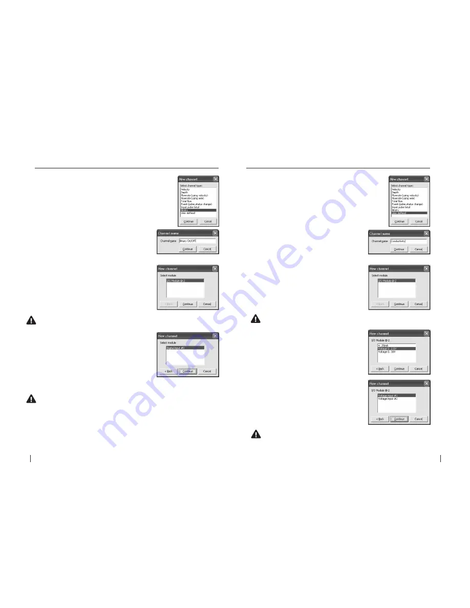
2.
The
“Channel name”
dialogue box will
appear. Enter a channel
“Name”
in to the text
field (16 character maximum). This
“name”
will
also be displayed on the HM 3000 main LCD if
enabled. Click
“Continue”.
3.
In the
“New channel”
dialogue box highlight
the
“I/O Module”
option from which the named
channel will receive its value. Click
“Continue”
and a new dialogue box will appear with the
available input types listed.
NOte: as a particular module’s input becomes fully utilised the module
will not appear on the “Select module” list.
4.
Select the
“Digital input”
type from the
“I/O
Module @ 2”
list.
NOte: as a particular module’s inputs are utilised the input will not
appear on the “I/O module” list. In the example above, the
“Digital input #3” will no longer be available.
5.
In this example the channel named
“Binary
On/Off”
will be calculated using a switch
attached to
“I/O Module @ 2”
on
“Digital input
#3”
. Click
“Continue”
to complete the new
channel. The
“Configure channels”
dialogue box
will re-appear with the new channel listed.
1.
Select the
“Depth”
channel type from the
“New
channel”
dialogue box and click
“Continue”.
21.1.11 Add a “Binary” channel type
- I/O card
2.
The
“Channel name”
dialogue box will
appear. Enter a channel
“Name”
in to the text
field (16 character maximum). This
“name”
will
also be displayed on the HM 3000 main LCD if
enabled. Click
“Continue”.
3.
In the
“New channel”
dialogue box highlight
the
“I/O Module”
option from which the named
channel will receive its value. Click
“Continue”
and a new dialogue box will appear with the
available input types listed.
NOte: as a particular module’s input becomes fully utilised the
module will not appear on the “Select module” list.
4.
Select the
“Voltage 0..2.5V”
or
“Voltage
0..30V”
input type from the
“I/O Module @ 2”
list.
Click
“Continue”
and then select the appropriate
input from which the named channel will receive
its value.
NOte: as a particular module’s inputs are utilised the input will
not appear on the “I/O module” list. In the example above, the
“Voltage input #1” will no longer be available.
5.
In this example the channel named
“Conductivity”
will be calculated using a sensor
attached to
“I/O Module @ 2”
on
“Voltage input
#1”
. Click
“Continue”
to complete the new
channel. The
“Configure channels”
dialogue box
will re-appear with the new channel listed.
1.
Select the
“User defined”
channel type from the
“New
channel”
dialogue box and click
“Continue”.
21.1.12 Add a “User defined” channel type
-
I/O card (Voltage)


