36
SeCtion b
SoFtware Manual
RetuRn to toC
MaCe HydRoMaCe 3000
Product Manual
37
RetuRn to toC
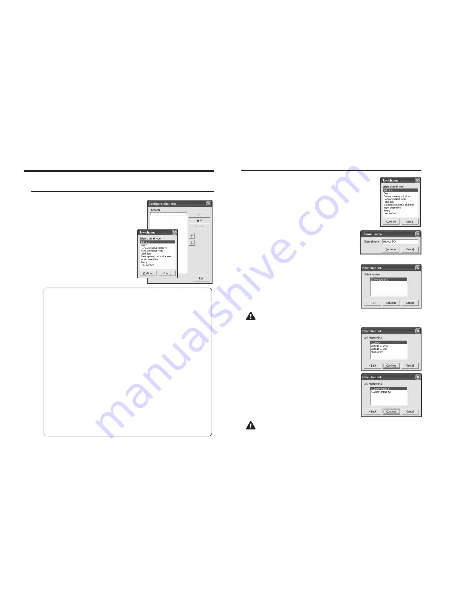
21.0 Configure channels
From the
“HM3000 Settings”
dialogue box
click
“Configure channel”
and the
“Configure
channels”
dialogue box will appear.
1.
Click
“Add”
and the
“New channel”
dialogue box will appear as shown.
Channel types
Description
Velocity:
This channel type MUST be used whenever the resultant
velocity measurement will be used in a flow rate calculation.
Depth:
This channel type MUST be used whenever the resultant
depth measurement will be used in a flow rate calculation.
Flowrate:
This channel type is used to calculate a flow rate based upon
the results obtained from configured velocity and depth
channels.
Flowrate:
This channel type is used to calculate a flow rate based upon
a depth channel and a selected weir type.
Total Flow:
This channel type is used to calculate an accumulated
positive or negative total based on the results obtained from
a configured flow rate channel.
Event:
This channel type is used to record time stamp data based on
pulse or status change events.
Input pulse total:
This channel type is used to totalise pulses such as totalising
flow meters and rain gauges.
Binary:
This channel type is used to monitor switch closure events
such as pump on/off status and/or rainfall gauges.
User Defined:
This channel type can be used when a 3rd party sensor with
digital/analogue output is to be configured. It should NOT
be used for velocity or depth sensors where the results are
required for a flow rate calculation.
21.1 adding a new channel
(using velocity)
(using weir)
(pulse, status change)
2.
The
“Channel name”
dialogue box will
appear. Enter a channel
“Name”
in to the text
field (16 character maximum). This
“name”
will
also be displayed on the HM 3000 main LCD if
enabled. Click
“Continue”.
1.
Select the
“Velocity”
channel type from the
“New
channel”
dialogue box and click
“Continue”.
21.1.1 Add a “Velocity” channel type -
I/O card (4-20mA)
3.
In the
“New channel”
dialogue box highlight
the
“I/O Module”
option from which the named
channel will receive its value. Click
“Continue”
and a new dialogue box will appear with the
available input types listed.
NOte: as a particular module’s input becomes fully utilised the
module will not appear on the “Select module” list.
4.
Select the
“4-20mA”
input type from the
“I/O
Module @ 2”
list. Click
“Continue”
and then select
the appropriate input from which the named
channel will receive its value.
NOte: as a particular module’s inputs are utilised the input will
not appear on the “I/O module” list. In the example above, the
“4..20ma input #1” will no longer be available.
5.
In this example the channel named
“Velocity
I/O”
will be calculated using a sensor attached
to
“I/O Module @ 2”
on
“4..20mA input #1”
. Click
“Continue”
to complete the new channel. The
“Configure channels”
dialogue box will re-appear
with the new channel listed.


