background image

215333

110

Revision A

1022666

A

C

B

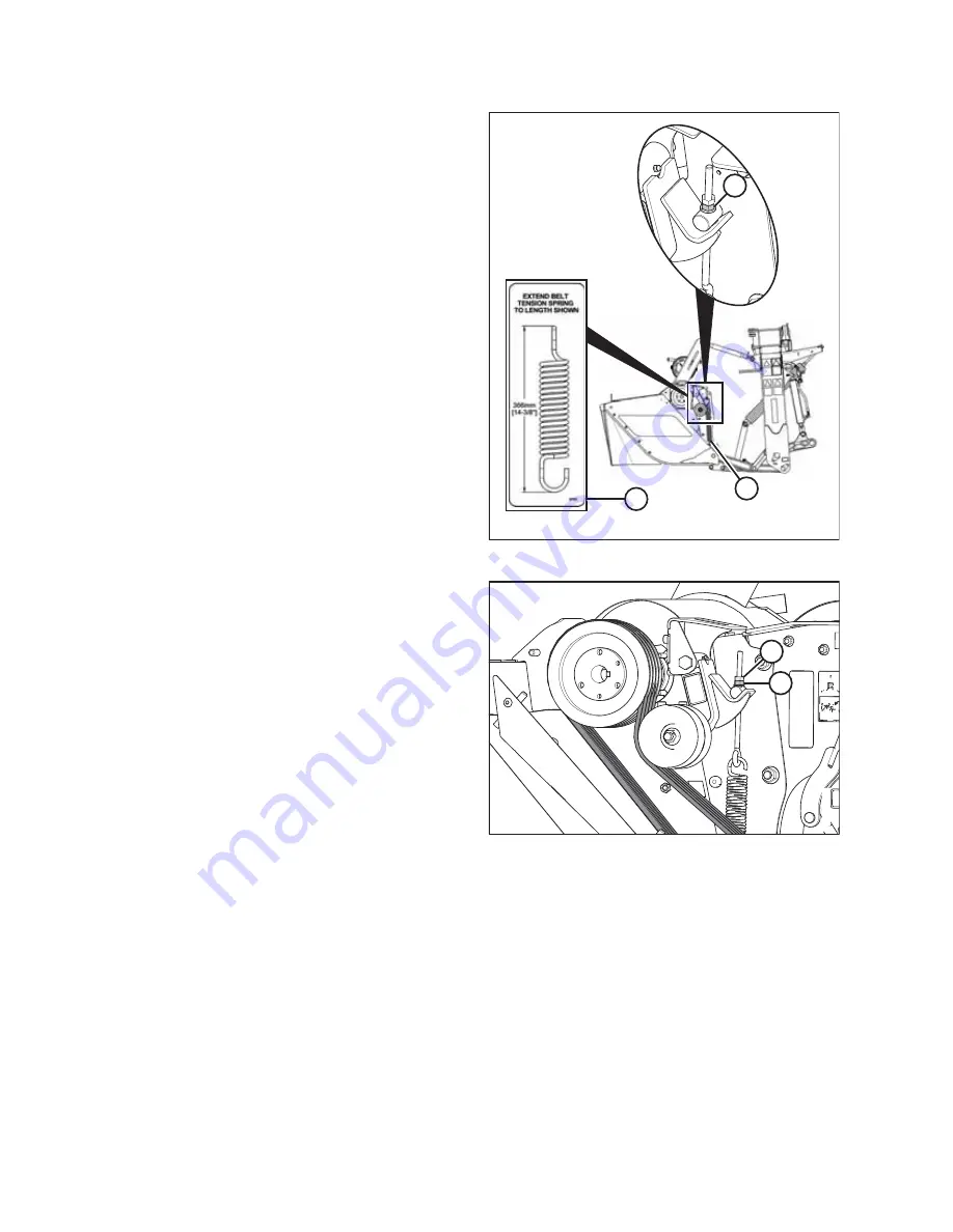
Figure 3.138: Spring Tension Decal

15. Measure the length of tensioner spring (A), and turn

adjuster nut (B) to adjust spring length to 36.5 cm
(14 3/8 in.) to conform with spring tension decal (C).

1033160

A

B

Figure 3.139: Conditioner Drive

16. Install jam nut (A).

17. Hold a wrench on adjuster nut (B) and turn jam nut (A)

clockwise into adjuster nut to lock the tension adjustment.

18. Verify that the pulleys run true and if any of the pulleys

wobble, return to Step

1, page 108

and repeat the

procedure to reinstall the taper locks on the affected
pulleys.

OPERATION

Содержание R1 Series

Страница 1: ...R1 Series Rotary Disc Pull Type Operator s Manual 215333 Revision A Original Instruction The Harvesting Specialists...

Страница 2: ...ation is based on the information available and in effect at the time of printing MacDon Industries Ltd makes no representation or warranty of any kind whether expressed or implied with respect to the...

Страница 3: ...ED DQDGD 5 6 Z W d D Z Z D D W E t D d E D E E K E K W E Z D D t K E K E K D t s D E K E K E K E Z D t d t W D E D s Z E K E K K E h W E W h Z D D t E d E E E K E K E Z D t d D E m E K E K d Z W D t D...

Страница 4: ...s E t s D E Z E K E K W E E Z D t WK D K d E E t E K E K Z D t E ZK E d E E K E K E Z D D t s s D E E K E K W E Z D t d D s h E K E K Z D t E D d E s W E K E K D D D Z D t E d E d E E h E K E K E E Z...

Страница 5: ...ations Failure to do so may compromise machine function and machine life and may result in a hazardous situation MacDon provides warranty for Customers who operate and maintain their equipment as desc...

Страница 6: ...nly Throughout Name Rotary Disc Pull Type was Pull Type Marketing Throughout Profiled out technical manual content Pubs Removing Cutterbar Deflectors page 93 Revised illustrations for new cutterbar de...

Страница 7: ...ovided below 1015306 A Rotary Disc Pull Type Serial Number Location A Rotary disc pull type serial number A Model year 1015307 A Hitch Serial Number Location A R113 Shown R116 Similar Hitch serial num...

Страница 8: ......

Страница 9: ...ponent Identification 25 2 3 Product Specifications 28 Chapter 3 Operation 31 3 1 Lift Cylinder Lock Out Valves 31 3 1 1 Engaging Locks 31 3 1 2 Disengaging Locks 32 3 2 Driveshields 33 3 2 1 Opening...

Страница 10: ...4 2 Converting between Field and Transport Modes 70 Converting from Transport to Field Mode Without Road Friendly Transport 70 Converting from Field to Transport Mode Without Road Friendly Transport 7...

Страница 11: ...ner 111 Positioning Rear Baffle Finger Conditioner 112 3 18 Haying Tips 113 3 18 1 Curing 113 3 18 2 Topsoil Moisture 113 3 18 3 Weather and Topography 113 3 18 4 Windrow Characteristics 114 3 18 5 Dr...

Страница 12: ...lades 171 Installing Disc Blades 172 4 4 8 Maintaining Quick Change Blade System 173 Inspecting Retaining Bolts 173 Inspecting Quick Change Plates 175 Replacing Quick Change Blades 176 4 4 9 Maintaini...

Страница 13: ...line Taper Pins 248 4 5 9 Driveline Guards 250 Removing Driveline Guards 250 Installing Driveline Guards 251 4 5 10 Conditioner Drive Belt 254 Inspecting Conditioner Drive Belt 254 Removing Conditione...

Страница 14: ...nd Carrier 291 4 9 Replacing Shield No Conditioner 294 4 9 1 Removing Discharge Shield No Conditioner 294 4 9 2 Installing Discharge Shield No Conditioner 295 Chapter 5 Options and Attachments 299 5 1...

Страница 15: ...aulic Fittings Adjustable 315 7 1 6 O Ring Boss Hydraulic Fittings Non Adjustable 317 7 1 7 O Ring Face Seal Hydraulic Fittings 318 7 1 8 Tapered Pipe Thread Fittings 319 7 2 Conversion Chart 320 7 3...

Страница 16: ......

Страница 17: ...indicates important safety messages in this manual and on safety signs on the machine This symbol means ATTENTION BECOME ALERT YOUR SAFETY IS INVOLVED Carefully read and follow the safety message acc...

Страница 18: ...ded will result in death or serious injury WARNING Indicates a potentially hazardous situation that if not avoided could result in death or serious injury It may also be used to alert against unsafe p...

Страница 19: ...Heavy gloves Wet weather gear Respirator or filter mask 1000005 Figure 1 3 Safety Equipment In addition take the following precautions Be aware that exposure to loud noises can cause hearing impairmen...

Страница 20: ...machine function and or safety It may also shorten the machine s life To avoid injury or death from unexpected startup of the machine ALWAYS stop the engine and remove the key from the ignition before...

Страница 21: ...achine Make sure all components are tight and that steel lines hoses and couplings are in good condition before applying pressure to hydraulic systems Keep hands feet clothing and hair away from all m...

Страница 22: ...high pressure Makeshift repairs will fail suddenly and create hazardous and unsafe conditions 1001207 Figure 1 12 Hydraulic Pressure Hazard Wear proper hand and eye protection when searching for high...

Страница 23: ...op Make sure the tire is correctly seated before inflating to operating pressure If the tire is not correctly positioned on the rim or is overinflated the tire bead can loosen on one side causing air...

Страница 24: ...r part displays the current safety sign Replacement safety signs are available from your MacDon Dealer Parts Department 1 7 1 Installing Safety Decals 1 Clean and dry the installation area 2 Decide ex...

Страница 25: ...gn Decal Locations 1014815 A B C D F G E Figure 1 17 Safety Sign Decal Locations Top View A MD 194466 B MD 247167 C MD 194465 D MD 184372 E MD 190546 F MD 113482 G MD 166466 1014816 A B C E D G F Figu...

Страница 26: ...E 1014817 A B C D Figure 1 19 Safety Sign Decal Locations Left Side A MD 113482 B MD 174436 C MD 259058 D MD 247166 E MD 171287 A 1014818 B Figure 1 20 Safety Sign Decal Locations Right Side A MD 1712...

Страница 27: ...11 Revision A 1014857 D E A D E C B F F B C Figure 1 21 Safety Sign Decal Locations Roll Conditioner A MD 190546 B MD 184385 C MD 184371 D MD 246959 E MD 246956 F NO STEP Symbol Imprinted on Shield S...

Страница 28: ...215333 12 Revision A 1022680 A B C D E D A B Figure 1 22 Safety Sign Decal Locations Finger Conditioner A MD 184385 B MD 184371 C MD 184422 D MD 190546 E NO STEP Symbol Imprinted on Shield SAFETY...

Страница 29: ...0 A B C D Figure 1 23 Safety Sign Decal Locations Hitch R116 PT Shown R113 PT Similar A MD 194464 B MD 113482 C MD 174436 D MD 259058 1024219 A B Figure 1 24 Safety Sign Decal Locations Transport A MD...

Страница 30: ...ts Disengage header drive put transmission in Neutral and wait for all movement to stop before leaving operator s position Stop the engine and remove the key from the ignition before servicing adjusti...

Страница 31: ...MD 174436 MD 174436 High pressure oil hazard WARNING To prevent serious injury gangrene or death Do NOT go near leaks Do NOT use finger or skin to check for leaks Lower load or relieve hydraulic press...

Страница 32: ...ne and during operation Keep riders off the machine Keep all shields in place and stay clear of moving parts Disengage header drive put transmission in Neutral and wait for all movement to stop before...

Страница 33: ...D 184422 MD 184422 Hand and arm entanglement hazard WARNING To prevent injury Stop engine and remove key before opening shield Do NOT operate without shields in place 1004138 Figure 1 34 MD 190546 MD...

Страница 34: ...ace Stand clear of rotary disc pull type while machine is running Disengage PTO stop engine and remove key before opening shield Stop engine and remove key before opening shield Blades may continue to...

Страница 35: ...emove key before opening shield Do NOT operate without shields in place 1004137 Figure 1 39 MD 246959 MD 246959 Pinch point hazard CAUTION To prevent injury Do NOT reach into pinch area 1010588 Figure...

Страница 36: ...covers Blades may continue to rotate after power is shut off Listen and look for evidence of rotation before opening shield 1023714 Figure 1 42 MD 259058 MD 259058 Off center tracking hazard WARNING T...

Страница 37: ...ravelling downhill Never attempt to get on or off a moving machine Do NOT get off the tractor while the pull type is in operation Stop forward movement of the tractor and stop the power take off To av...

Страница 38: ...fe and proper use Review the manual and all safety related items with all Operators annually Be alert for other Operators not using recommended procedures or not following safety precautions Immediate...

Страница 39: ...rop Hex key A tool of hexagonal cross section used to drive bolts and screws that have a hexagonal socket in head internal wrenching hexagon drive also known as an Allen key and various other synonyms...

Страница 40: ...bolt or screw usually measured in Newtons N or pounds lb TFFT Turns from finger tight Torque The product of a force X lever arm length usually measured in Newton meters Nm or foot pounds lbf ft Torqu...

Страница 41: ...Light x2 E Red Tail Brake Light x2 F Forward Baffle Control G Front Curtains H Driveshield J Carrier Frame K Rear Deflector Control L Optional Transport System Figure 2 2 Rotary Disc Pull Type with Fi...

Страница 42: ...ocking Cylinder D Skid Shoe E Side Deflector F Rear Curtain Figure 2 4 Hitch and Driveline R116 Shown R113 Similar 1016445 A B C D E F G H J K A Control Hoses B Primary Driveline C Hose Support D Head...

Страница 43: ...215333 27 Revision A Figure 2 5 Hitch Options 1026392 A B C A Tractor Two Point Hitch Adapter B Tractor Drawbar Hitch Adapter C Tractor Utility Hitch Adapter PRODUCT OVERVIEW...

Страница 44: ...23 ft 4 in 8580 mm 28 ft 2 in Transport length with RFT 8407 mm 27 ft 7 in 9856 mm 32 ft 4 in Estimated weight with steel roll conditioner without RFT 2409 kg 5300 lb 2740 kg 6040 lb Estimated weight...

Страница 45: ...flectors Two drum type converging Four drum type converging Drives Tractor Power Take Off PTO 35 mm 1 3 8 in dia 21 spline or 44 mm 1 3 4 in dia 20 spline Mechanical Gearbox and driveline Conditioner...

Страница 46: ...cutting 8 15 km h 5 10 mph Recommended transport3 30 km h 20 mph Tractor Requirements Power Take Off PTO power minimum 74 kW 100 hp 93 kW 125 hp Hydraulics4 Pressure 13 71 MPa 2000 psi Hydraulics4 Con...

Страница 47: ...gine remove key and engage lift cylinder lock out valves before going under machine for any reason IMPORTANT Connect hoses so that moving the cylinder control lever backward raises the rotary disc pul...

Страница 48: ...er lock out valves before going under machine for any reason 1023736 1023736 A Figure 3 3 Lift Cylinder Lock Out Valve in Open Position 1 Open lock out valve A on each lift cylinder by turning the han...

Страница 49: ...lace and secured 1008667 Figure 3 5 Left Driveshield NOTE Images shown in this procedure are for the left driveshield the right driveshield is similar 1010707 A B C Figure 3 6 Left Driveshield 1 Remov...

Страница 50: ...n A 1010709 A Figure 3 8 Driveshield 3 Pull top of driveshield A away from the header to open NOTE For improved access lift driveshield off the pins at the base of the shield and lay the shield on the...

Страница 51: ...own in this procedure are for the left driveshield the right driveshield is similar 1010711 A B Figure 3 9 Driveshield and Latch 1 Position driveshield onto pins at base of driveshield if necessary 2...

Страница 52: ...pull types sold outside of North America have latches on the cutterbar door IMPORTANT Replace curtains if they become worn or damaged For instructions refer to 4 4 2 Maintaining Curtains page 140 3 3...

Страница 53: ...ays stop the engine and remove the key from the ignition before leaving the operator s seat for any reason 1 If both doors need to be opened center the pull type beneath the hitch 2 Shut down the engi...

Страница 54: ...on the latch 3 3 3 Closing Cutterbar Doors CAUTION To avoid injury keep hands and fingers away from corners of doors when closing 1011300 A Figure 3 16 Cutterbar Doors and Curtains 1 Pull down on door...

Страница 55: ...protective clothing and personal safety devices that could be necessary throughout the day Don t take chances Remove foreign objects from the machine and surrounding area 1001351 Figure 3 17 Safety E...

Страница 56: ...t are missing broken or not working correctly NOTE Use proper procedure when searching for pressurized fluid leaks Refer to 4 6 1 Checking Hydraulic Hoses and Lines page 274 2 Clean all lights and ref...

Страница 57: ...justing the Drawbar WARNING To avoid bodily injury or death from the unexpected startup of the machine always stop the engine and remove the key before making adjustments to the machine 1 Shut down th...

Страница 58: ...bodily injury or death from the unexpected startup of the machine always stop the engine and remove the key before making adjustments to the machine 1 Shut down the engine and remove the key from the...

Страница 59: ...nexpected startup of the machine always stop the engine and remove the key before making adjustments to the machine 1030361 A B Figure 3 22 Rotary Disc Pull Type Hitch 1 Remove lynch pin A from clevis...

Страница 60: ...e tractor power take off PTO 7 Pull back collar B on primary driveline A and push the primary driveline until it locks Release collar 8 Route safety chain C from the rotary disc pull type through chai...

Страница 61: ...guration 1 Position the tractor and align hitch arms A with hitch adapter B 2 Shut down the engine and remove the key from the ignition 3 Remove lynch pins C and washers from the hitch adapter 4 Secur...

Страница 62: ...iveline Attached to Tractor PTO 8 Position primary driveline A onto the tractor s PTO shaft making sure that the driveline is approximately level 9 Pull back the collar on driveline A and push the dri...

Страница 63: ...1030339 A Figure 3 32 Repositioning Hitch Stand 14 Rotate stand A upward and into storage position 1030338 B A Figure 3 33 Hitch Stand in Storage Position 15 Insert pin A and secure stand B in storag...

Страница 64: ...cylinder hose red collar with 1 to the tractor s hydraulic receptacle Connect the second hose blue collar with 1 only when the transport is installed Refer to Table 3 5 page 48 to confirm the system...

Страница 65: ...ion B is used to supply power to the rotary disc pull type brake lights 2 Connect rotary disc pull type wiring harness connector C to the tractor receptacle NOTE The connector is designed to fit tract...

Страница 66: ...onnection 1023703 A B C Figure 3 39 Control Box 6 Connect control box power wire A to the tractor s power supply as follows Connect wire C with the red tag to tractor power Connect wire B with no tag...

Страница 67: ...A 1022647 A Figure 3 40 Control Box Interior NOTE The transport control box has a 10 amp fuse A inside If this fuse fails the transport function will not activate 7 Place the control box inside the tr...

Страница 68: ...pull type onto blocks or leave it raised IMPORTANT If leaving the rotary disc pull type in the raised position close steering valve and both left right lift cylinder lock out valves 3 Shut down the e...

Страница 69: ...ends and electrical connector in hose support A at front of hitch as shown 1026353 A B Figure 3 43 Jack Storage 8 Pull pin B securing jack A at storage location and remove the jack 1026352 A B Figure...

Страница 70: ...r off the tractor power take off shaft and rest the driveline on the hook not shown 1026350 A B C D Figure 3 46 Rotary Disc Pull Type Hitch 14 Remove lynch pin D and clevis pin C 15 Raise the hitch us...

Страница 71: ...ype onto blocks or leave the pull type raised If leaving the pull type in the raised position close the lift cylinder safety valves Refer to 3 1 1 Engaging Locks page 31 3 Shut down the engine and rem...

Страница 72: ...at the front of the hitch as shown NOTE Control box A is also stored at the front of the hitch 1011121 A Figure 3 50 Driveline 8 Pull back collar A on the driveline slide the coupler off of the tracto...

Страница 73: ...he rotary disc pull type 15 Start the tractor and lower the hitch to take the weight off the tractor hitch points 16 Shut down the engine and remove the key from the ignition 1003844 A B 1003844 A B 1...

Страница 74: ...ng or interfering parts WARNING Before investigating an unusual sound or attempting to correct a problem shut off tractor engage parking brake and remove key IMPORTANT Be especially alert until you be...

Страница 75: ...before engaging the power take off PTO Never leave tractor seat with the PTO engaged 1 Move the rotary disc pull type up to the standing crop and slowly engage the PTO 2 Ensure tractor PTO is running...

Страница 76: ...on the ground This control is used to raise the rotary disc pull type to clear obstacles and windrows during field operation to adjust the rotary disc pull type height for maintenance and to raise the...

Страница 77: ...ge the power take off Park on level ground if possible Lower the rotary disc pull type fully Place all controls in NEUTRAL or PARK Engage the park brake Stop engine and remove key from ignition Wait f...

Страница 78: ...A to steer the rotary disc pull type into the desired path of travel Move lever forward to position B to steer the rotary disc pull type to the right Move lever backward to position C to steer the rot...

Страница 79: ...e of the tractor 3 13 2 Operating on the Left Side of the Tractor 1003562 Figure 3 61 Left Side Operation Follow the step below to steer the rotary disc pull type to the left side of the tractor 10105...

Страница 80: ...g procedure is intended as a guide for developing a turning procedure for your tractor and rotary disc pull type Specific distances are not given due to the different steering capabilities of various...

Страница 81: ...contact the hitch 4 Position the tractor so it is straddling the last cut windrow As the rotary disc pull type finishes turning steer it back towards the uncut crop align the rotary disc pull type wit...

Страница 82: ...NOTE For ease of operation both steering control levers can be activated with one hand and held until the steering cylinder completes its stroke 3 Proceed to position B and start turning the tractor b...

Страница 83: ...ate warning to operators of other vehicles Do NOT transport the rotary disc pull type on a road or highway at night or in reduced visibility conditions such as rain or fog Ensure that hitch on transpo...

Страница 84: ...Figure 3 68 Drawbar Jack in Storage Position 4 If equipped with a drawbar hitch Move jack A to the storage position on the side of the hitch align the mounting holes and secure with pin B 1030341 A B...

Страница 85: ...s refer to 3 7 3 Connecting Hydraulics page 48 1023734 1023734 A Figure 3 72 Cylinder Lock Out Valve in Closed Position 8 Raise the rotary disc pull type fully and close the lift cylinder lock out val...

Страница 86: ...nverting from Field to Transport Mode Without Road Friendly Transport page 71 Converting from Field to Transport Mode with Road Friendly Transport page 72 Converting from Transport to Field Mode with...

Страница 87: ...startup of the machine always stop the engine and remove the key from the ignition before leaving the operator s seat for any reason 1 Raise rotary disc pull type 2 Move rotary disc pull type fully t...

Страница 88: ...r from transport mode until all people animals and objects are clear of the unit s rotational range DANGER Stop the power take off PTO before converting the unit into transport mode The cutting discs...

Страница 89: ...e rotary disc pull type 2 Following the steps on field to transport decal A move transport switch to lower position C and ensure that light B is illuminated 1016411 Figure 3 79 Raising Rotary Disc Pul...

Страница 90: ...tion and ensure that the light is NOT illuminated The hitch swing circuit is now deactivated and the transport circuit is active 1016414 A B C Figure 3 82 Transport Assembly Rotation 6 Operate the hit...

Страница 91: ...nce the latch has engaged do NOT operate any hydraulic circuits 1023678 Figure 3 84 Hydraulic Lockout 10 Close the steering lock out valve and the two lift cylinder lock out valves by turning the hand...

Страница 92: ...alve by turning handle A to the closed position 90 to the hose Repeat on opposite side 1023658 B A Figure 3 87 Transport Mode 11 Activate hazard lights A on the rotary disc pull type Ensure all lights...

Страница 93: ...5333 77 Revision A 1023707 1023707 A B C Figure 3 88 Control Box 13 Once field to transport conversion A is complete leave the switch in upper position C Ensure that light B is NOT illuminated OPERATI...

Страница 94: ...r doors are properly closed before converting the machine from field to transport mode 1 Clear bystanders from the area and start tractor Do NOT operate the rotary disc pull type 1023691 A B C Figure...

Страница 95: ...ylinder lock out Open the valve by turning handle A to the open position in line with the hose Repeat on opposite side 1023686 Figure 3 93 Raising Rotary Disc Pull Type 4 While the light is NOT illumi...

Страница 96: ...wing cylinder and the transport deploy cylinder During the transition continue to hold the hitch swing lever in the active position to allow oil to be supplied to the two cylinders sequentially 102368...

Страница 97: ...endly Transport page 72 1 Before transporting the rotary disc pull type with a tractor ensure the machine is prepared for transport Refer to 3 14 1 Preparing Rotary Disc Pull Type for Transport page 6...

Страница 98: ...inflated IMPORTANT Do NOT exceed 32 km h 20 mph 3 14 4 Transport Lighting Lighting With Road Friendly Transport Option 1015026 A B Figure 3 99 Lighting Locations with Road Friendly Transport The rotar...

Страница 99: ...rn signals Red lights B located on the inboard side of the amber lights function as both tail and brake lights Refer to 3 7 4 Connecting Electrical Wiring Harness page 49 for information about connect...

Страница 100: ...nd speed 3 15 4 Ground Speed page 91 Conditioning roll type 3 16 Conditioning Roll Type page 97 Conditioning finger type 3 17 Conditioning Finger Type page 107 3 15 1 Float Float springs are normally...

Страница 101: ...y disc pull type angle float and tilt 2 Raise the header fully 3 Shut down the engine and remove the key from the ignition 1030284 A Figure 3 102 Cylinder Lock Out Valve Closed Position 4 Close the ro...

Страница 102: ...bolt counterclockwise away from spring to decrease float Repeat on opposite side Table 3 9 Float Setting Starting Point Model Conditioner Type Length of Exposed Thread None 280 290 mm 11 11 5 32 in R...

Страница 103: ...up of mud and soil inside the rotary disc pull type which can lead to poor crop flow and increased wear on cutting components Lowering the skid shoes and decreasing the cutterbar angle increases the c...

Страница 104: ...he key from the ignition 3 Engage the lift cylinder lock out valves For instructions refer to 3 1 1 Engaging Locks page 31 4 Loosen bolts C 5 Remove bolts nuts and washers D 6 Raise or lower the skid...

Страница 105: ...215333 89 Revision A 1014667 A B C D D C Figure 3 108 Skid Shoes R116 PT OPERATION...

Страница 106: ...eat for any reason 1 Lower the rotary disc pull type fully 2 Shut down the engine and remove the key from the ignition 1019447 A B Figure 3 110 Mechanical Center Link 3 Loosen nut A 4 Decrease flatten...

Страница 107: ...round speed to suit your specific crop Refer to your tractor operator s manual for instructions on changing ground speed CAUTION Reduce speed when turning crossing slopes or traveling over rough groun...

Страница 108: ...215333 92 Revision A 1027203 Figure 3 112 Ground Speed for R113 and R116 PT A Acres Hour B Hectares Hour C Kilometers Hour D Miles Hour E R116 PT F R113 PT OPERATION...

Страница 109: ...lectors must NOT be used with the finger conditioner option 1 Raise the rotary disc pull type fully 2 Shut down the engine and remove the key from the ignition 3 Engage the lift cylinder lock out valv...

Страница 110: ...all bolt B shared with the rock guard at the outboard end of deflector 7 Secure the deflector to the cutterbar with three button socket head M10 bolts C and lock nuts Bolts are inserted into the cutte...

Страница 111: ...pull type and reinstall three bolts A and nuts Tighten nuts 6 Repeat for opposite side 7 Close cutterbar doors For instructions refer to 3 3 3 Closing Cutterbar Doors page 38 Removing Tall Crop Divide...

Страница 112: ...Figure 3 118 Deflector and Hardware 4 Remove three bolts A and remove deflector B 5 Reinstall three bolts A 6 Repeat for opposite side 7 Close cutterbar doors For instructions refer to 3 3 3 Closing C...

Страница 113: ...produce these results Steel rolls can be operated over a larger range of roll gap settings intermesh and are therefore suited to a wider range of crops alfalfa to thicker stemmed cane type crops using...

Страница 114: ...tending above the jam nut on the adjustment rods can be used as an approximation of roll gap but does NOT provide consistent roll gap measurements Roll gap factory setting is 6 mm 1 4 in If adjustment...

Страница 115: ...e and remove the key from the ignition 1018573 A B Figure 3 121 Roll Gap Adjustment 3 Loosen upper jam nut A on both sides of the conditioner attachment 4 Turn lower nut B counterclockwise until the u...

Страница 116: ...ignition 1018573 A B Figure 3 122 Roll Gap Adjustment 3 Loosen jam nut A on both sides of the conditioner 4 Turn lower nut B counterclockwise until the upper roll rests on the lower roll Ensure the ro...

Страница 117: ...jam nut A on both sides of conditioner 4 Turn spring drawbolt B clockwise to tighten spring C and INCREASE roll tension 5 Turn spring drawbolt B counterclockwise to loosen spring C and DECREASE roll t...

Страница 118: ...eath from unexpected start up of machine always stop the engine and remove the key from the ignition before leaving the operator s seat for any reason 1 Shut down the engine and remove the key from th...

Страница 119: ...it stops Make a second mark B on the yoke flange and align it with the mark on the gearbox flange 1033176 A B Figure 3 128 Conditioner Drive 7 Determine center point A between the two marks on the yo...

Страница 120: ...onditions rain sun humidity and wind Type and yield of crop Available drying time Method of processing bales silage and green feed A wider windrow will generally dry faster and more evenly resulting i...

Страница 121: ...e Deflector and Adjuster Bar 1 Loosen locking handle A 2 Slide adjuster bar B along adjuster plate C to the desired deflector position and engage bar B into a notch in the adjuster plate 3 Tighten loc...

Страница 122: ...follow these steps WARNING To avoid injury or death from unexpected start up of machine always stop the engine and remove the key from the ignition before leaving the operator s seat for any reason 10...

Страница 123: ...e are seven clearance settings from 8 to 71 mm 5 16 to 2 3 4 in The baffle is located in front of and above the finger rotor Set the clearance depending on crop volume and the desired level of conditi...

Страница 124: ...always stop the engine and remove the key from the ignition before leaving the operator s seat for any reason NOTE For 900 rpm mount the larger pulley on the conditioner roll timing gearbox and the sm...

Страница 125: ...second pulley 8 Swap the pulleys 1010614 1010615 1010615 A Figure 3 136 Drive Belt and Pulleys on Left Side Rotary Disc Pull Type 9 Slip taper lock bushing A onto the shaft at the same depth measureme...

Страница 126: ...rm with spring tension decal C 1033160 A B Figure 3 139 Conditioner Drive 16 Install jam nut A 17 Hold a wrench on adjuster nut B and turn jam nut A clockwise into adjuster nut to lock the tension adj...

Страница 127: ...Haying Tips page 113 A narrower windrow may be preferable for ease of pick up and when drying is not critical for example when cutting for silage or green feed Positioning Side Deflectors Finger Cond...

Страница 128: ...expected startup of the machine always stop the engine and remove the key from the ignition before leaving the operator s seat for any reason To adjust the position of the rear baffle follow these ste...

Страница 129: ...Use a moisture tester or estimate level If ground is wet due to irrigation wait until soil moisture drops below 45 If ground is wet due to frequent rains cut hay when weather allows and let the forag...

Страница 130: ...raked can lengthen drying time by a full day If practical set forming shields to produce a narrower windrow that the machine can straddle NOTE Driving on the windrow in high yield crops may be unavoid...

Страница 131: ...quire adjustment The float springs are NOT used to level the rotary disc pull type If the rotary disc pull type is NOT level check the tire pressure and ensure proper inflation For inflation instructi...

Страница 132: ...d movement of the tractor and stop the power take off PTO 2 Raise the rotary disc pull type fully 3 Shut down the engine and remove the key from the ignition 4 Engage lift cylinder lock out valves For...

Страница 133: ...215333 117 Revision A 1010658 Figure 3 145 Cutterbar Doors in Closed Position 7 Close cutterbar doors For instructions refer to 3 3 3 Closing Cutterbar Doors page 38 OPERATION...

Страница 134: ......

Страница 135: ...Record page 123 to keep track of your scheduled maintenance 4 1 Recommended Safety Procedures Park on level surface when possible Securely block wheels if rotary disc pull type is parked on an incline...

Страница 136: ...uishers are located and know how to use them 1000009 Figure 4 5 Safety Around Equipment Keep the service area clean and dry Wet or oily floors are slippery Wet spots can be dangerous when working with...

Страница 137: ...rs 1 Lower the rotary disc pull type fully If you need to perform service in the raised position and always close lift cylinder lock out valves For instructions refer to 3 1 Lift Cylinder Lock Out Val...

Страница 138: ...zed according to service intervals If more than one interval is specified for a service item e g 100 hours or annually service the machine at whichever interval is reached first When servicing the mac...

Страница 139: ...241 First 5 Hours Check for loose hardware Refer to 7 1 Torque Specifications page 309 Check conditioner drive belt tension Refer to Inspecting Conditioner Drive Belt page 254 First 10 Hours Then Dai...

Страница 140: ...versal joints Refer to 4 3 5 Lubricating the Rotary Disc Pull Type page 128 S Lubricate roller conditioner bearings Refer to 4 3 5 Lubricating the Rotary Disc Pull Type page 128 S Lubricate conditione...

Страница 141: ...g Lubricant Cutterbar Conditioner Drive Gearbox T Gearbox page 261 Check roll timing gearbox lubricant Refer to Checking and Changing Oil in Conditioner Roll Timing Gearbox page 259 Check header swive...

Страница 142: ...rbox page 261 Change header swivel gearbox and hitch swivel gearbox lubricant Refer to Draining Lubricant from the Header Swivel Gearbox and Hitch Swivel Gearbox page 269 and Adding Lubricant to the H...

Страница 143: ...and change pull type drive gearbox lubricant 4 5 12 Pull Type Drive Gearbox T Gearbox page 260 250 Hours Check and change swivel gearbox lubricant 4 5 13 Header Swivel Gearbox and Hitch Swivel Gearbox...

Страница 144: ...any missing or loose hardware For information refer to 7 1 Torque Specifications page 309 6 Lubricate the rotary disc pull type thoroughly leaving excess grease on fittings to keep moisture out of be...

Страница 145: ...rom the ignition before leaving the operator s seat for any reason 1 Open driveshields at the ends of the rotary disc pull type to access greasing points For instructions refer to 3 2 1 Opening Drives...

Страница 146: ...15333 130 Revision A Every 25 Hours Figure 4 7 Grease Location Every 25 Hours 1022894 A B 25 25 25 3x25 25 3x25 A Conditioner Drive Idler B Bearing for Finger Type Conditioner MAINTENANCE AND SERVICIN...

Страница 147: ...215333 131 Revision A Figure 4 8 Grease Location Every 25 Hours 1022895 A B A Hitch Steering Pivot B Tractor Hitch Pivot MAINTENANCE AND SERVICING...

Страница 148: ...ore information NOTE Use high temperature extreme pressure EP2 performance with 10 max molybdenum disulphide NLGI Grade 2 lithium base unless otherwise specified 1010653 1010653 A B Figure 4 9 Driveli...

Страница 149: ...Friendly Transport Wheel Frame Pivot Figure 4 11 Grease Location Every 25 Hours 1011432 A B A Pull Type Lift Linkage Left B Pull Type Lift Linkage Right NOTE Use high temperature extreme pressure EP2...

Страница 150: ...0 Hours NOTE Use high temperature extreme pressure EP2 performance with 1 max molybdenum disulphide NLGI grade 2 lithium base unless otherwise specified Figure 4 12 Grease Location Every 50 Hours 1011...

Страница 151: ...ontal remove check plug from swivel gearbox and verify that oil slightly runs out when removed Figure 4 13 Lubrication Location Every 100 Hours 1008672 A B C D A Check Plug Swivel Gearbox B Check Plug...

Страница 152: ...earbox T Gearbox 12 B Bearing Field Wheel 2 Places 13 C Bearing Road Friendly Transport Option 2 Places MAINTENANCE AND SERVICING 12 Remove check plug from conditioner drive gearbox as shown and check...

Страница 153: ...nformation 4 4 3 Lubricating Cutterbar page 146 Checking and Changing Oil in Conditioner Roll Timing Gearbox page 259 Figure 4 15 Lubrication Location Every 250 Hours 1008679 A C B A Cutterbar Lubrica...

Страница 154: ...nd D For information refer to 4 5 13 Header Swivel Gearbox and Hitch Swivel Gearbox page 267 Figure 4 16 Lubrication Location Every 250 Hours 1008687 A B C D A Upper Forward Gearbox B Lower Forward Ge...

Страница 155: ...bber curtains provide access to the cutterbar area and reduce the risk of objects being ejected Always keep doors closed during operation Inspecting Cutterbar Doors 1 Ensure that the door operates smo...

Страница 156: ...portant safety features that reduce the potential for thrown objects Always keep these curtains down when operating the rotary disc pull type WARNING To reduce the risk of personal injury and machine...

Страница 157: ...bolt studs 3 Remove aluminum liner B 4 Remove curtain C Installing Cutterbar Door Curtains The procedure for installing cutterbar door curtains is the same for both doors 1022626 B A C D E Figure 4 23...

Страница 158: ...ening Cutterbar Doors North America page 36 1011310 A B Figure 4 25 Inboard Curtain 2 Remove two M10 carriage head bolts A and nuts securing curtain assembly B to the pull type and remove curtain asse...

Страница 159: ...and Brackets 2 Install curtain onto weld and bolt studs on center shield install two curtain brackets B and secure with four nuts A 3 Torque hardware to 28 Nm 21 lbf ft IMPORTANT To avoid damaging bo...

Страница 160: ...des 1003631 Figure 4 30 Cutterbar Doors R1 Series Rotary Disc Pull Type 1 Open cutterbar doors For instructions refer to 3 3 1 Opening Cutterbar Doors North America page 36 1010696 A Figure 4 31 Left...

Страница 161: ...slide out the bracket B and remove curtain A Installing Outboard Curtains The procedure for installing outboard curtains is the same for both sides 1003631 Figure 4 33 Cutterbar Doors R1 Series Rotary...

Страница 162: ...r bolts A nuts and large washers to secure outboard curtain to endsheet Torque bolts to 39 Nm 29 lbf ft 4 4 3 Lubricating Cutterbar Checking and Adding Lubricant Cutterbar WARNING To avoid bodily inju...

Страница 163: ...to 3 3 1 Opening Cutterbar Doors North America page 36 or 3 3 2 Opening Cutterbar Doors Export Latches page 37 1003631 Figure 4 36 Cutterbar Doors R1 Series Rotary Disc Pull Type 5 Open cutterbar door...

Страница 164: ...he engine and raise the rotary disc pull type fully 12 Shut down the engine and remove the key from the ignition 13 Close the lift cylinder lock out valves on both sides of the rotary disc pull type V...

Страница 165: ...This will improve access to the drain plug located in the end cap of the cutterbar To remove the outboard rock guard refer to Removing Outboard Rock Guards page 184 NOTE The reinforced rock guards are...

Страница 166: ...cant leaks could result 7 Allow sufficient time for lubricant to drain then reinstall cutterbar plug A NOTE Do NOT flush the cutterbar 8 Fill the cutterbar with lubricant before operating the rotary d...

Страница 167: ...ft end 4 Lower the rotary disc pull type onto the blocks 5 Shut down the engine and remove the key from the ignition 6 Remove access plug A from the raised end of the cutterbar and add the EXACT amoun...

Страница 168: ...d must be replaced if severely damaged or worn IMPORTANT If holes appear in a cutterbar disc replace the disc immediately Do NOT attempt to repair the cutterbar discs Always use factory replacement pa...

Страница 169: ...s excessive wear and disc distortion Replace as required 4 Inspect cutterbar disc edges E for cracks excessive wear and edge distortion Replace as required NOTE Cutterbar discs are NOT repairable and...

Страница 170: ...linder lock out valves For instructions refer to 3 1 1 Engaging Locks page 31 1003631 Figure 4 47 Cutterbar Doors R1 Series Rotary Disc Pull Type 4 Open cutterbar doors For instructions refer to 3 3 1...

Страница 171: ...from unexpected start up or fall of a raised machine stop engine remove key and engage lift cylinder lock out valves before going under machine for any reason WARNING Exercise caution when working aro...

Страница 172: ...and secure assembly with four M12 bolts and washers C Torque bolts to 85 Nm 63 lbf ft WARNING Ensure the cutterbar is completely clear of foreign objects Foreign objects can be ejected with considerab...

Страница 173: ...shear pins Refer to 4 4 13 Replacing Cutterbar Spindle Shear Pin page 212 to replace shear pin 1019153 A B C Figure 4 54 Cutterbar Spindles IMPORTANT Spindles that rotate clockwise have right leading...

Страница 174: ...c pull type fully NOTE To prevent oil from spilling from the cutterbar when removing disc spindles ensure the rotary disc pull type is on a flat level surface and is tilted all the way back 3 Shut dow...

Страница 175: ...rbar disc B IMPORTANT Blades are rotation specific Switch entire disc when swapping spindles 1011389 A Figure 4 58 Spacer Plate 9 Remove spacer plate A 1011375 A B Figure 4 59 Left Spindle Hub and Har...

Страница 176: ...lt in the following Disc blades of co rotating discs hitting each other Disc blades of diverging discs hitting adjacent discs Check clearance timing before tightening spindle to the cutterbar Turn dis...

Страница 177: ...cause serious injury Exercise caution and wear gloves when working with blades 1 Park the machine on a flat level surface 2 Lower the rotary disc pull type fully NOTE To prevent oil from spilling fro...

Страница 178: ...se spindles rotate clockwise and counterclockwise spindles with machined grooves rotate counterclockwise IMPORTANT The offset gear design makes it possible to install spindles that rotate in the wrong...

Страница 179: ...specific It is necessary to switch entire disc when swapping spindles 13 Position disc A on spindle ensuring that it is positioned at a 90 angle in relation to the adjacent discs NOTE Turn disc A by...

Страница 180: ...ch spindle and disc pair is designed to rotate in one direction and must be changed as sets when altering crop flows 1011125 Figure 4 71 R113 and R116 PT Cutterbars Reducing or increasing the number o...

Страница 181: ...and are identified by machined grooves on the spindle gear shaft B and nut C If the spindle position in the cutterbar has changed the rotational direction of that spindle MUST remain the same that is...

Страница 182: ...ree Crop Streams NOTE Refer to Removing Cutterbar Spindles page 158 and Installing Cutterbar Spindles page 160 To change R113 PT 8 disc spindle rotation from three crop streams B to one crop stream A...

Страница 183: ...op streams B to one crop stream A Swap disc spindle 4 with disc spindle 7 4 4 7 Maintaining Disc blades 1004001 A Figure 4 75 Disc blades Each disc has two blades A attached at opposite ends that are...

Страница 184: ...3888 Figure 4 76 Disc Blades A Blade Wear to Center Line B Elongated Hole C Maximum Elongation 21 mm 13 16 in 1 Check daily that the disc blades are securely attached to the disc 2 Inspect blades for...

Страница 185: ...or blade attachment hardware can be ejected during machine operation and may cause personal injury or machine damage Inspect blade attachment hardware each time blades are changed For instructions re...

Страница 186: ...eplace bolt if Bolt has been removed and installed five times Head A is worn flush with bearing surface of blade Diameter of bolt neck is worn B 3 mm 1 8 in Bolt is cracked C Bolt is visibly distorted...

Страница 187: ...p engine remove key and engage lift cylinder lock out valves before going under machine for any reason CAUTION Disc blades have two sharp cutting edges that can cause serious injury Exercise caution a...

Страница 188: ...olts 6 Clean debris from blade attachment area 7 Remove nut A and discard IMPORTANT Nuts are one time use only When flipping or changing a blade replace using a NEW nut only 8 Remove shoulder bolt B a...

Страница 189: ...result in serious injury or machine damage 1010658 Figure 4 85 R1 Series Rotary Disc Pull Type 4 Close cutterbar doors For instructions refer to 3 3 3 Closing Cutterbar Doors page 38 4 4 8 Maintaining...

Страница 190: ...f the gauge is used to check the material thickness of the retaining bolts section D of the gauge is used to check the outer radius of the quick change plate 1026425 A Figure 4 88 Checking Retaining B...

Страница 191: ...one point The wear limit must be checked with gauge A 1026451 A B C D Figure 4 89 Change Tool and Gauge 1 Gauge A is located on change tool B NOTE Section C of the gauge is used to check the material...

Страница 192: ...ter radius of gauge A the quick change plate must be replaced 1026432 A B Figure 4 92 Gauge and Change Plate Unaligned Replacing Quick Change Blades If optional quick change blade kit is installed rep...

Страница 193: ...c B 1025409 A B C D D E Figure 4 95 Installing Quick Change Blade 5 Pull down on tool A open disc B and remove old blade D from blade bolt E Push tool A upward to return disc B to the closed position...

Страница 194: ...in pairs to ensure proper disc balance Inspecting Accelerators DANGER To avoid bodily injury or death from unexpected start up or fall of a raised machine stop the engine remove the key and engage the...

Страница 195: ...ing fasteners Removing Accelerators DANGER To avoid bodily injury or death from unexpected start up or fall of a raised machine stop engine remove key and engage lift cylinder lock out valves before g...

Страница 196: ...ng edges that can cause serious injury Exercise caution and wear gloves when working with blades 1004047 A C B Figure 4 101 Accelerator Removal 5 Remove nut A flange bolt B and disc blade C from disc...

Страница 197: ...B C D Figure 4 103 Accelerator Install 1 Place a wooden block between two cutterbar discs to prevent disc rotation while tightening blade bolts IMPORTANT Accelerators are unidirectional both clockwis...

Страница 198: ...osing Cutterbar Doors page 38 4 4 10 Rock Guards The machine is equipped with rock guards at each cutting disc location Rock guards prevent the cutterbar from digging into the ground and protect the d...

Страница 199: ...thickness 5 Check for loose or missing fasteners tighten or replace fasteners as needed Removing Inboard Rock Guards 1003622 A Figure 4 108 Inboard Rock Guards 1 Remove two hex head screws washers an...

Страница 200: ...n top Removing Outboard Rock Guards DANGER To avoid bodily injury or death from unexpected start up or fall of a raised machine stop engine remove key and engage lift cylinder lock out valves before g...

Страница 201: ...by sliding it forward 9 Repeat Steps 4 page 185 to 8 page 185 at the opposite side of the cutterbar Installing Outboard Rock Guards DANGER To avoid bodily injury or death from unexpected start up or f...

Страница 202: ...k guard towards the center of the header until the tabs on the front of the rock guard are supported by the cutterbar 1027047 A B Figure 4 115 Outboard Rock Guard 9 Using a rubber mallet tap rock guar...

Страница 203: ...Large Drums B Small Non Driven Drum C Small Driven Drum IMPORTANT The inboard drums B and C are approximately 73 mm 2 3 8 in smaller in diameter than the outboard drums A IMPORTANT Measure drum size t...

Страница 204: ...A B Figure 4 121 R116 PT Drums A Small Driven Drum B Large Non Driven Drum 4 Inspect for damage and wear and replace if drums are worn at the center to 50 or more of their original thickness Do NOT re...

Страница 205: ...from the ignition before leaving the operator s seat for any reason WARNING Exercise caution when working around the blades Blades are sharp and can cause serious injury Wear gloves when handling bla...

Страница 206: ...ange head bolts A and remove vertical driveshield B 1024659 A B B Figure 4 125 Driveline Shield 5 Remove two M10 hex flange head bolts B and cover plate A 1024925 A B C Figure 4 126 Driveline Shield 6...

Страница 207: ...M10 hex flange head bolts C and vertical shield A 1024921 A B B Figure 4 128 Driveline Shield 8 Remove eight M8 hex flange head bolts A and two drum shields B 1011137 A A B C Figure 4 129 Driveline 9...

Страница 208: ...m disc assembly B Installing Small Driven Drum and Driveline R116 PT WARNING To avoid bodily injury or death from unexpected startup of the machine always stop the engine and remove the key from the i...

Страница 209: ...ck cover of this manual NOTE For clarity the illustration shows a cutaway view of the drum and tube shield 6 Insert driveline B at an angle and guide it past hub drive C and drum D 7 Insert splined sp...

Страница 210: ...a bead of medium strength threadlocker Loctite 243 or equivalent around the threads of one M10 hex flange head bolt B and two M10 hex flange head bolts C Use bolts B and C to secure the vertical shie...

Страница 211: ...plate A and vertical shield E Torque hardware to 61 Nm 45 lbf ft 14 Tighten bolts B and D 1024929 A B A A A Figure 4 139 Driveline Shield 15 Position vertical driveshield B as shown at right Apply a...

Страница 212: ...engine and remove the key from the ignition before leaving the operator s seat for any reason WARNING Exercise caution when working around the blades Blades are sharp and can cause serious injury Wea...

Страница 213: ...tup of the machine always stop the engine and remove the key from the ignition before leaving the operator s seat for any reason WARNING Exercise caution when working around the blades Blades are shar...

Страница 214: ...ssembly to spindle Torque hardware to 55 Nm 40 lbf ft WARNING Ensure the cutterbar is completely clear of foreign objects Foreign objects can be ejected with considerable force when the machine is sta...

Страница 215: ...maller in diameter than the large outboard drums C and D Large drums measure 250 mm 9 7 8 in across Small drums measure 187 mm 7 3 8 in across Inspecting Large Drums R113 or R116 PT Inspect drums dail...

Страница 216: ...50 or more of their original thickness Do NOT repair drums 5 Examine drums for large dents Replace dented drums to prevent an imbalance in the cutterbar 6 Tighten or replace loose or missing fasteners...

Страница 217: ...ing around the blades Blades are sharp and can cause serious injury Wear gloves when handling blades NOTE Illustrations show the left drum and driveline 1 Shut down the engine and remove the key from...

Страница 218: ...r plate B 1011327 A B C Figure 4 153 Top Plate and Drum Top 5 Remove four M10 hex flange head bolts A and remove top plate B and drum top C 1021850 A B B C Figure 4 154 Vertical Shield 6 Remove one M1...

Страница 219: ...Drive and Driveline Assembly 8 Remove four M12 hex flange head bolts A and spacers securing driveline assembly B to hub drive C 1011143 A Figure 4 157 Driveline 9 Slide driveline A downwards and tilt...

Страница 220: ...death from unexpected start up or fall of a raised machine stop engine remove key and engage lift cylinder lock out valves before going under machine for any reason WARNING Exercise caution when work...

Страница 221: ...nual NOTE The driveline U joints were greased at the factory and are considered to be lubricated for life No further lubrication is required NOTE For clarity the illustration shows a cutaway view of t...

Страница 222: ...ly a bead of medium strength threadlocker Loctite 243 or equivalent around the threads of one M10 hex flange head bolt B and two M10 hex flange head bolts C Use bolts B and C to secure the vertical sh...

Страница 223: ...cover plate A and vertical shield E Torque hardware to 61 Nm 45 lbf ft 14 Tighten bolts B and D 1011078 A B Figure 4 167 Driveline Shield 15 Position vertical driveshield B as shown at right Apply a b...

Страница 224: ...chine stop engine remove key and engage lift cylinder lock out valves before going under machine for any reason WARNING Exercise caution when working around the blades Blades are sharp and can cause s...

Страница 225: ...otation while loosening blade bolts 3 Remove eight M8 bolts A and washers securing cover B to the non driven drum and remove cover 1024794 B A Figure 4 171 Non Driven Drum 4 Remove four M10 bolts A in...

Страница 226: ...ound the blades Blades are sharp and can cause serious injury Wear gloves when handling blades 1 Shut down the engine and remove the key from the ignition 1017492 A Figure 4 172 Non Driven Spindle 2 E...

Страница 227: ...bf ft WARNING Ensure the cutterbar is completely clear of foreign objects Foreign objects can be ejected with considerable force when the machine is started and may result in serious injury or machine...

Страница 228: ...ll become unloaded Do NOT replace the spindle due to excessive play Check play after torquing spindle nut and replacing damaged shear pins Removing Cutterbar Spindle Shear Pin DANGER To avoid bodily i...

Страница 229: ...PT similar 7 Depending on the type of disc with a broken shear pin refer to the applicable disc removal procedure To remove cutterbar disc A refer to Removing Cutterbar Discs page 153 To remove driven...

Страница 230: ...ear shaft A Spindles that rotate counterclockwise have left leading threading and machined grooves on the spindle gear shaft B and nut C If the spindle position in the cutterbar has changed the rotati...

Страница 231: ...1 Use the safecut spindle nut wrench and remove nut A 1016456 A B Figure 4 184 Cutterbar Spindle 12 Remove shear pins B Do NOT damage the pin bore on the pinion 13 Remove hub A 14 Check the nut and hu...

Страница 232: ...h blades 1016458 A B C Figure 4 185 Cutterbar Spindle 1 Fill the space above the bearing with grease 2 Place hub A on spindle C 3 Install shear pins B NOTE Ensure that the ends of shear pins B do not...

Страница 233: ...done the proper torque will NOT be applied to the nut 7 Position safecut spindle nut wrench B on spindle nut C Torque nut to 300 Nm 221 lbf ft 8 Return safecut spindle nut wrench B to the left shield...

Страница 234: ...tions refer to Installing Large Driven Drums and Driveline R113 or R116 PT page 204 Install non driven drum C For instructions refer to Installing Large Non Driven Drums R113 or R116 PT page 210 WARNI...

Страница 235: ...NOT operate the machine without the driveshields in place and secured 1021830 A Figure 4 193 Left Driveshield NOTE Images shown in this procedure are for the left driveshield the right driveshield is...

Страница 236: ...ld and Latch 2 Insert the flat end of tool A into latch B and turn it counterclockwise to unlock 1010709 A Figure 4 196 Driveshield 3 Pull the top of driveshield A away from the pull type and lift off...

Страница 237: ...ft driveshield the right driveshield is similar 1021884 B B A C Figure 4 197 Driveshield and Latch 1 Position driveshield A onto pins B at the base of the driveshield 2 Push the driveshield to engage...

Страница 238: ...Removing Driveshields page 219 1010701 A Figure 4 200 Backside of Driveshield 2 Remove hex nut A and flat washer securing latch to the backside of the driveshield replace latch if worn or damaged and...

Страница 239: ...ver clamps A using a screwdriver or similar prying tool 2 Unhook safety chain B from hitch and ensure that chain is secured to the shield cone and metal plate 1010607 A Figure 4 203 Driveline Shield C...

Страница 240: ...e B 3 Attach safety chain C to hitch and ensure that chain is secured to the shield cone and metal plate 4 5 3 Hitch Driveline Phasing To reduce hitch driveline vibration the drivelines should be inst...

Страница 241: ...n the R116 rotary disc pull type refer to Figure 4 207 page 225 the U joint on middle driveline B must be aligned 90 to the U joints on front driveline A and clutch driveline C 1023646 A B C Figure 4...

Страница 242: ...void bodily injury or death from unexpected startup of the machine always stop the engine and remove the key from the ignition before leaving the operator s seat for any reason 1 Shut down the engine...

Страница 243: ...Primary Driveline WARNING To avoid bodily injury or death from unexpected startup of the machine always stop the engine and remove the key from the ignition before leaving the operator s seat for any...

Страница 244: ...s moving then check before start of every season NOTE For all other joints that use the taper pin the pin must be recessed approximately 9 11 mm 3 8 7 16 in 1008383 1008383 A Figure 4 213 Shield Clipp...

Страница 245: ...no maintenance is required For lubrication instructions refer to 4 4 3 Lubricating Cutterbar page 146 Removing Hitch Driveline WARNING To avoid bodily injury or death from unexpected startup of the m...

Страница 246: ...Driveline Cover and Shield Installed at Center Support 3 Remove two bolts A and slide the metal shield B away from center support 1017500 A Figure 4 218 Mid Driveshaft Yoke 4 Remove mid drive yoke A f...

Страница 247: ...late B to the center support and then remove metal plate B 1019530 A Figure 4 220 Spacer 6 Remove spacer A 1008501 A B C D A A Figure 4 221 Ball Bearing and Flanges 7 Support driveline and remove five...

Страница 248: ...t NOTE There are three hitch drivelines installed on a R116 Rotary Disc Pull Type 12 Remove driveline guard if necessary For instructions refer to Removing Driveline Guards page 250 Installing Hitch D...

Страница 249: ...ft end of the driveline onto the hitch support bracket and support the driveline to hold it in place IMPORTANT Ensure locking collar A is on the backside of the support bracket 6 Install two long bolt...

Страница 250: ...lts as shown 1008497 A B Figure 4 229 Spacer Installed at Center Support 12 Install spacer A with cutout in spacer aligned with grease fitting B 1008506 A B C Figure 4 230 Metal Plate Attached to Cent...

Страница 251: ...re with three screws A 17 Install metal shield C with two bolts B NOTE There are three hitch drivelines for installation on the R116 rotary disc pull type 1010764 A Figure 4 232 Clutch Driveline Insta...

Страница 252: ...needs replacing Follow regular lubrication procedures and ensure all driveline taper pins are torqued as instructed For instructions refer to 4 4 3 Lubricating Cutterbar page 146 and 4 5 8 Inspecting...

Страница 253: ...from the ignition 1010777 A B C Figure 4 234 Driveline Shield Cone 2 Release two lever clamps A using a screwdriver or similar prying tool 3 Unhook safety chain B from hitch and ensure that chain is...

Страница 254: ...two lever clamps A on the shield cone installed at the header swivel gearbox 9 Remove driveline guard if necessary For instructions refer to Removing Driveline Guards page 250 1010780 A Figure 4 238 D...

Страница 255: ...e 251 1008474 A Figure 4 239 Driveline and Gearbox 3 Position driveline onto the gearbox shaft as shown at right 4 Clean the taper pin threads 5 Install taper pin into yoke with groove on pin aligned...

Страница 256: ...D as shown NOTE Before installing the driveline refer to 4 5 3 Hitch Driveline Phasing page 224 to ensure proper orientation 1019429 A Figure 4 243 R113 PT Clutch Driveline 10 Move the shield cone to...

Страница 257: ...h may slip prematurely As part of the break in procedure the clutch spring pressure should be released and the header engaged This intentional slippage of the clutch will wear in and seat the friction...

Страница 258: ...m 8 Shut down the engine and remove the key from the ignition 1022509 A B Figure 4 248 Driveline and Gearbox 9 Inspect the clutch Horizontal mark A across the friction discs should no longer line up w...

Страница 259: ...A Figure 4 250 Driveline Shield Cone 1 Release two lever clamps A on the shield cone installed at the header swivel gearbox 2 Slide shield away from gearbox 1022510 A Figure 4 251 Clutch Bolts 3 Back...

Страница 260: ...ht Once the discs are nearing the 17 75 mm 0 70 in dimension check discs for looseness Do NOT tighten the discs excessively Try to achieve a balance between the clutch slipping during excessive loadin...

Страница 261: ...ways stop the engine and remove the key from the ignition before leaving the operator s seat for any reason 1015179 1015179 A Figure 4 256 Lower Left View of Rotary Disc Pull Type 1 Shut down the engi...

Страница 262: ...osen nut A so that taper pin threads are recessed inside the nut 6 Tap nut A with a hammer to loosen the taper pin and release driveline yoke B from the shaft 7 Repeat for the opposite end of the driv...

Страница 263: ...bar Doors North America page 36 1015171 A B Figure 4 260 Cross Driveline Yoke 3 Position driveline yoke B as shown on both ends of the cross driveline 4 Install taper pin so groove on pin is aligned w...

Страница 264: ...pins are located at three places A along the hitch driveshaft Torque each pin to 150 Nm 110 lbf ft every 25 hours until it no longer moves and then check at the beginning of every season 1015099 A A A...

Страница 265: ...aces B on the cross shaft driveline Torque each pin to 150 Nm 110 lbf ft every 25 hours until it no longer moves and then check at the beginning of every season 1015101 B B Figure 4 263 Cross Shaft Dr...

Страница 266: ...the operator s seat for any reason 1 Shut down the engine and remove the key from the ignition 1015311 A Figure 4 264 Driveline 2 Remove driveline A from which the guard is going to be removed For in...

Страница 267: ...5 Remove shield support A from outer cone B Installing Driveline Guards WARNING To avoid bodily injury or death from unexpected startup of the machine always stop the engine and remove the key from t...

Страница 268: ...d ensure that grease fitting C faces the drive tube 1010801 A B C Figure 4 269 Shield Support and Outer Cone 4 Install shield support A into outer cone B and ensure that grease fitting C is inserted i...

Страница 269: ...wered tool to tighten screws 1019457 A Figure 4 272 Driveline Guard IMPORTANT If installing a replacement guard ensure chain A is short enough that it does NOT wrap around the driveline guard 1015311...

Страница 270: ...NG To avoid bodily injury or death from unexpected startup of the machine always stop the engine and remove the key from the ignition before leaving the operator s seat for any reason 1 Lower the rota...

Страница 271: ...er spring A and ensure spring length is 366 mm 14 3 8 in in accordance with spring tension decal B If spring length requires adjustment refer to Installing Conditioner Drive Belt page 257 7 Close the...

Страница 272: ...Shut down the engine and remove the key from the ignition 1010709 A Figure 4 277 Left Driveshield 3 Remove left driveshield A For instructions refer to Removing Driveshields page 219 1022898 A B C D F...

Страница 273: ...riven pulley C and then onto drive pulley B Ensure the belt is in the pulley grooves NOTE If necessary loosen jam nut and adjuster nut D to relieve spring tension 1022669 A B C D Figure 4 280 Spring T...

Страница 274: ...riveshields page 221 4 5 11 Conditioner Roll Timing Gearbox 1008384 A Figure 4 282 Conditioner Roll Timing Gearbox Conditioner roll timing gearbox A is located inside the drive compartment at the righ...

Страница 275: ...the gearbox oil level when the oil is warm If the oil is cold idle the machine for approximately 10 minutes prior to checking 1010816 A Figure 4 283 Right Driveshield 1 Open right driveshield A For i...

Страница 276: ...round oil level plug B on the inboard side of the gearbox 9 Place a 1 liter 1 05 qts US container underneath the conditioner gearbox 10 Remove oil drain plug A using a hex key 11 Allow sufficient time...

Страница 277: ...rive gearbox set the rotary disc pull type s skid shoes in the fully raised position For instructions refer to Adjusting Cutting Height page 88 3 Shut down the engine and remove the key from the ignit...

Страница 278: ...socket 10 Ensure lubricant level is to the line on dipstick 11 If necessary add gear lubricant to gearbox through dipstick hole A Refer to the manual s inside back cover for lubricant information 12...

Страница 279: ...cant when the lubricant is warm If the lubricant is cold idle the machine for approximately 10 minutes prior to draining 1 Lower the rotary disc pull type fully 2 Shut down the engine and remove the k...

Страница 280: ...lange head bolts A and cover plate B 1011327 A B C Figure 4 293 Top Plate and Drum Top 6 Remove four M10 hex flange head bolts A top plate B and drum top C 1011079 A B Figure 4 294 Vertical Shield 7 R...

Страница 281: ...ow sufficient time for lubricant to drain replace drain plug A and tighten 10 Properly dispose of used oil 1011079 A B Figure 4 296 Vertical Shield 11 Position vertical shield B as shown and install a...

Страница 282: ...plate A and vertical shield E 15 Tighten bolts B and D 1011078 A B Figure 4 299 Vertical Driveshield 16 Install vertical driveshield B using four M10 hex flange head bolts A WARNING Ensure the cutter...

Страница 283: ...ming gearbox and the hitch swivel gearbox that transfers power from the tractor to the header swivel gearbox Both gearboxes consist of upper and lower gearboxes If either of the gearboxes requires rep...

Страница 284: ...th header swivel and hitch swivel gearboxes and and must be done on both upper and lower gearboxes 1 Lower rotary disc pull type fully NOTE Hitch swivel and header swivel gearbox orientations are not...

Страница 285: ...vel and hitch swivel gearboxes and must be done on both upper and lower gearboxes 1 Shut down the engine and remove the key from the ignition 1011329 A B Figure 4 303 Gearbox Drain Plug 2 Place a 2 li...

Страница 286: ...lug B 3 Remove check plug A and breather filler plug B 4 Ensure the lubricant level is visible or begins to drain through check port A and add gear lubricant to gearbox through port B as required Refe...

Страница 287: ...Nm 120 lbf ft using the tightening sequence shown at right IMPORTANT Whenever a wheel is installed check torque after 1 hour of operation Removing Wheels WARNING To avoid injury or death from unexpect...

Страница 288: ...not attached to towing vehicle 3 Position jack under frame leg B 4 Loosen wheel bolts slightly 5 Operate jack to raise wheel off ground 6 Place blocks or a stand under frame leg 7 Remove wheel bolts...

Страница 289: ...k tire pressure and adjust as required For instructions refer to Inflating Tires page 273 Inflating Tires 1000020 Figure 4 310 Overinflated Tire WARNING Service tires safely A tire can explode during...

Страница 290: ...few hours by a doctor familiar with this type of injury or gangrene may result 1001205 Figure 4 313 Testing for Hydraulic Leaks Use a piece of cardboard or paper to search for leaks IMPORTANT Keep hy...

Страница 291: ...rews 3 Remove two Phillips screws A from the fixture and remove the plastic lens 4 Replace the bulb trade 1157 and reinstall the plastic lens and screws Replacing Amber Hazard Signal Light Fixture 101...

Страница 292: ...nting Bracket 1 Cut cable ties A securing harness covering to light 2 Retrieve connections from inside harness covering approximately 150 mm 6 in from light and disconnect wires not shown If necessary...

Страница 293: ...out valves before going under machine for any reason WARNING Exercise caution when working around the blades Blades are sharp and can cause serious injury Wear gloves when handling blades 1 Lower the...

Страница 294: ...cross the conditioning baffle which strips away the waxy coating from plants The degree to which the crop is conditioned as it passes through the conditioner is controlled by the clearance between the...

Страница 295: ...60 A A Figure 4 322 Driveshields 4 Remove left and right driveshields A For instructions refer to Removing Driveshields page 219 1003631 Figure 4 323 Cutterbar Doors 5 Open the cutterbar doors For ins...

Страница 296: ...9 Remove the right driveshield For instructions refer to Removing Driveshields page 219 10 Inspect right rotor bearing A for signs of wear or damage Contact your MacDon dealer if bearing needs to be...

Страница 297: ...1 Connect the rotary disc pull type to the tractor For instructions refer to 3 7 Attaching Rotary Disc Pull Type to the Tractor page 43 2 Start the tractor and center the rotary disc pull type behind...

Страница 298: ...8 Start the engine 9 Lower the rotary disc pull type fully 10 Shut down the engine and remove the key from the ignition 11 Check that float adjuster bolts B are loose Back off adjuster bolts as requir...

Страница 299: ...20 nut A washers and hex head bolt B securing carrier leg C to the left end of the header 1030468 A B C Figure 4 335 Mechanical Center Link 17 If equipped with mechanical center link Remove clevis pin...

Страница 300: ...C to the gearbox 22 Lift steering arm C off the gearbox and secure the arm to hitch D with a strap or wire 23 Reinstall hex head bolts A and spacers B into the gearbox 24 Disconnect aft driveline E fr...

Страница 301: ...orklift or equivalent lifting device and attach chains to lugs B on the conditioner Use a chain rated for overhead lifting with a minimum working load of 1135 kg 2500 lb DANGER To prevent the conditio...

Страница 302: ...wn NOTE Access to upper bolts C is easiest from the rear of the conditioner 1030622 A Figure 4 343 Roll Conditioner Inboard Right Side 5 For roll conditioners Move baffle adjustment handle A to the fu...

Страница 303: ...Lift conditioner A off rotary disc pull type header B and move the conditioner away from the work area 1022570 A Figure 4 347 Deflector Location NOTE If installing a finger conditioner or if deflector...

Страница 304: ...instructions refer to Installing Cutterbar Deflectors page 94 NOTE If you are replacing a roll conditioner and deflector plates A are already installed on the machine proceed to Step 1 page 288 10153...

Страница 305: ...s For instructions refer to Installing Conditioner Drive page 289 Installing Conditioner Drive This procedure describes the installation of conditioner drive components If installing a conditioner on...

Страница 306: ...ssembly A as shown and secure with M16 x 120 bolt B and nut C Torque nut C to 51 Nm 38 lbf ft 1022672 A B C D E F G Figure 4 356 Tensioner 6 Install spring A into rear hole B for a finger conditioner...

Страница 307: ...inner steel sleeve of the bushing and the header brackets If there is a gap install washer 1 2 mm 0 047 in thick on both sides of the carrier leg to minimize the gap 4 Align left carrier leg A with h...

Страница 308: ...1030468 A B C Figure 4 361 Mechanical Center Link 15 If equipped with mechanical center link Undo the strapping or wire securing center link B to the carrier frame 16 If equipped with mechanical cent...

Страница 309: ...For instructions refer to Installing Driveshields page 221 1014366 A B C D E Figure 4 364 Electrical Harness 26 If a transport system is installed reconnect electrical harness A to lights B and secure...

Страница 310: ...ull type fully and extend the center link to maximize the space between shield A and carrier frame B 1023734 1023734 A Figure 4 367 Lift Cylinder Lock Out Valves 2 Close lift cylinder lock out valves...

Страница 311: ...tate shield A 90 and move it away from the carrier frame 4 9 2 Installing Discharge Shield No Conditioner Follow these steps to install the shielding on a rotary disc pull type configured without a co...

Страница 312: ...the closed position 90 angle to the hose 1015063 A Figure 4 373 Shield Rotated 3 Rotate shield A and pass it between the field wheels and the carrier frame toward the rotary disc pull type 1010880 A B...

Страница 313: ...d flat washers to secure shield B to panel C Ensure the bolt heads face inboard 1023736 1023736 A Figure 4 376 Lift Cylinder Lock Out Valves Open Position 6 Open lift cylinder lock out valves A on bot...

Страница 314: ......

Страница 315: ...ll crop dividers attach to the ends of the rotary disc pull type for clean crop dividing and cutterbar entry in tall crops The kit includes left and right dividers and attachment hardware MD B5800 5 1...

Страница 316: ...Tractor Utility Hitch Adapter 1010856 Figure 5 4 Tractor Utility Hitch Adapter The Tractor Utility Hitch Adapter allows the rotary disc pull type to connect to a tractor drawbar regardless of install...

Страница 317: ...lade kit allows you to change blades quickly using a blade change tool that separates the disc assembly Kits include all hardware and installation instructions Available for factory configured R1 PT S...

Страница 318: ...suited to a wide range of crops including alfalfa and thicker stemmed cane type crops A replacement steel intermeshing roller conditioner can be ordered for the R1 Series Rotary Disc Pull Type MD B575...

Страница 319: ...ll type to cut closer to ground 3 15 3 Adjusting Cutterbar Angle page 90 Symptom Strips of uncut crop left on field Bent or dull disc blades Replace blades 4 4 7 Maintaining Disc blades page 167 Build...

Страница 320: ...eight varies from one side to the other Float not properly balanced Adjust rotary disc pull type float 3 15 1 Float page 84 Symptom Not cutting short enough in down crop Broken bent or dull blades Rep...

Страница 321: ...ging behind end drums Ground speed too slow Increase ground speed 3 15 4 Ground Speed page 91 Symptom Bunching or poorly formed windrows Forming shields not properly adjusted Adjust forming shields 3...

Страница 322: ...20 Unplugging the Rotary Disc Pull Type page 116 Material wrapped around spindle Remove disc and remove material 3 20 Unplugging the Rotary Disc Pull Type page 116 Cutting too low in rocky field cond...

Страница 323: ...to one side Rotary disc pull type dragging on one end and pulling to that side Adjust rotary disc pull type flotation on both ends 3 15 1 Float page 84 Low tire pressure on one side Check and correct...

Страница 324: ......

Страница 325: ...regular nuts by f 0 65 Self tapping screws Standard torque is to be used NOT to be used on critical or structurally important joints 7 1 1 SAE Bolt Torque Specifications Torque values shown in followi...

Страница 326: ...2 105 116 77 86 5 8 11 144 160 107 118 3 4 10 259 286 192 212 7 8 9 413 456 306 338 1 8 619 684 459 507 A 1004958 B C D Figure 7 3 Bolt Grades A Nominal Size B SAE 8 C SAE 5 D SAE 2 Table 7 3 SAE Grad...

Страница 327: ...8 11 299 330 221 345 3 4 10 531 587 393 435 7 8 9 855 945 633 700 1 8 1165 1288 863 954 7 1 2 Metric Bolt Specifications 1001370 1001370 A Figure 7 5 Bolt Grades Table 7 5 Metric Class 8 8 Bolts and C...

Страница 328: ...65 72 48 53 14 2 0 104 115 77 85 16 2 0 161 178 119 132 20 2 5 314 347 233 257 24 3 0 543 600 402 444 1001370 1001370 A Figure 7 7 Bolt Grades Table 7 7 Metric Class 10 9 Bolts and Class 10 Free Spin...

Страница 329: ...5 105 8 1 25 26 29 19 21 10 1 5 51 57 38 42 12 1 75 90 99 66 73 14 2 0 143 158 106 117 16 2 0 222 246 165 182 20 2 5 434 480 322 356 24 3 0 750 829 556 614 7 1 3 Metric Bolt Specifications Bolting int...

Страница 330: ...ten nut E with other wrench to torque shown 5 Assess final condition of connection Table 7 10 Flare Type Hydraulic Tube Fittings SAE Dash Size Thread Size in Torque Value14 Flats from Finger Tight FFF...

Страница 331: ...ar as possible 3 Check that O ring A is NOT on threads and adjust if necessary 4 Apply hydraulic system oil to O ring A 1003432 D A E B C Figure 7 12 Hydraulic Fitting 5 Install fitting B into port un...

Страница 332: ...13 106 115 4 7 16 20 19 21 14 15 5 1 2 20 21 33 15 24 6 9 16 18 26 29 19 21 8 3 4 16 46 50 34 37 10 7 8 14 75 82 55 60 12 1 1 16 12 120 132 88 97 14 1 3 8 12 153 168 113 124 16 1 5 16 12 176 193 130 1...

Страница 333: ...able 7 12 page 317 6 Check final condition of fitting Table 7 12 O Ring Boss ORB Hydraulic Fittings Non Adjustable SAE Dash Size Thread Size in Torque Value16 Nm lbf ft lbf in 2 5 16 24 6 7 53 62 3 3...

Страница 334: ...rque fittings according to values in Table 7 13 page 318 NOTE If applicable hold hex on fitting body E to prevent rotation of fitting body and hose when tightening fitting nut D 6 Use three wrenches w...

Страница 335: ...ped connector typically 45 or 90 is aligned to receive incoming tube or hose assembly Always finish alignment of fitting in tightening direction Never back off loosen pipe threaded connectors to achie...

Страница 336: ...ressure megapascal MPa x 145 038 pounds per square inch psi Pressure bar Non SI bar x 14 5038 pounds per square inch psi Torque Newton meter Nm x 0 7376 pound feet or foot pounds lbf ft Torque Newton...

Страница 337: ...215333 321 Revision A 7 3 Converting Transport Decal 1026295 A B A Converting From Field to Transport B Converting From Transport to Field REFERENCE...

Страница 338: ......

Страница 339: ...p polyurethane rolls 99 steel rolls 100 checking roll gap polyurethane rolls 97 roll tension 101 adjusting 101 roll timing 101 adjusting 102 checking 102 type of conditioning finger type See finger co...

Страница 340: ...awbar hitch adapter 42 drive systems 219 conditioner drive belts 254 drivelines 224 clutch driveline 236 cross driveline 245 driveline phasing See drivelines drivelines 224 clutch driveline 236 instal...

Страница 341: ...224211 260 263 glossary 23 greasing decals 128 every 100 hours 135 every 25 hours 130 every 250 hours 137 every 50 hours 134 greasing procedures 129 maintenance schedule records 123 ground speed 91 GV...

Страница 342: ...pull type drive gearbox MD 221748 or MD 307211 checking gearbox oil 259 drive T gearbox checking and adding lubricant 261 MD 224211 261 recommended lubricants 329 lubrication every 100 hours 135 every...

Страница 343: ...ne rolls 99 steel rolls 100 roll tension 101 adjusting 101 roll timing 101 adjusting 102 checking 102 roll type conditioning See roll conditioners rotary disc pull type leveling 115 maintenance and se...

Страница 344: ...ching with two point hitch 43 45 definition 23 detaching from two point hitch 55 detaching rotary disc pull type 52 preparing for rotary disc pull type 41 setting up tractor adjusting drawbar 41 tract...

Страница 345: ...e specified SAE Multipurpose High temperature extreme pressure EP performance with 10 max molybdenum disulphide NLGI Grade 2 lithium base Driveline slip joints Lubricant Gear Lubricant SAE 80W 90 High...

Страница 346: ...16 891 7313 f 816 891 7323 LLC MacDon Russia Ltd 123317 Moscow Russia 10 Presnenskaya nab Block C Floor 5 Office No 534 Regus Business Centre t 7 495 775 6971 f 7 495 967 7600 MacDon Australia Pty Ltd...

Отзывы: