11
Figure 13
STEP 7&8 with the rest of the knives.
enough to just hold the knife in place. Repeat
pad of the knife setting jog. Snug the gib bolts tight
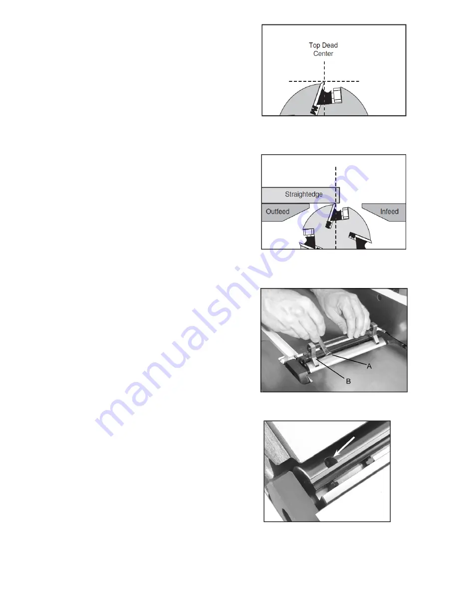
knife is set correctly, it will bearly touch the middle
screws to raise or lower the knife. When the
cutterhead(Fig. 13) and rotate the jack
jack screws through the access holes in the
the cutterhead over the blade. Find the
Loosen cutterhead gib bolt (A, Fig. 12)
8. Place the knife setting gauge (B, Fig. 12) on
by turning clockwise as viewed from the infeed
table as it is at the back of the table.
is at the same height at the front of the
It must have its knives parallel
it will
After the outfeed table has been set,
Figure 12
Figure 11
should look like Figure 11. Use care when
edge (C, Fig. 9) on the outfeed table and
9). Counter-clockwise will cause the
3. Loosen table lock screw (A, Fig. 9) and
is at top-dead-center(TDC), as shown
cutterhead pulley until one of the knives
Figure 10
table. (Fig. 15)
5. If fence is not square to table, release lock
handle (B, Fig. 14), loosen nut (D, Fig. 14),
and turn bolt (E, Fig. 14) until fence is
square to table.
6. Tighten nut (D, Fig. 14) to retain the setting.
Tighten lock handle (B, Fig. 14).
Figure 15
2. Rotate the cutterhead by turning the
raise the outfeed table to the height of blade
number one by turning handwheel (B, Fig.
outfeed table to raise. Clockwise will cause
the outfeed table to lower.Set a straight
across the cutterhead.
in Fig.10
4. Position of the table and straight edge
handling the straight edge near the blades
so as not to damage them.
5. When the outfeed table and blade number
one (or knife insert) are the same height,
tighten table lock screw.
need no further adjustments to the
cutterhead – skip steps 6 through 9 below.
with the outfeed table. Proceed as follows:
6. Bring the straight edge forward to the front
of the outfeed table and confirm that blade
7. If blade is higher or lower at one point,
table.


