background image

10

table so it extends over the cutterhead. 

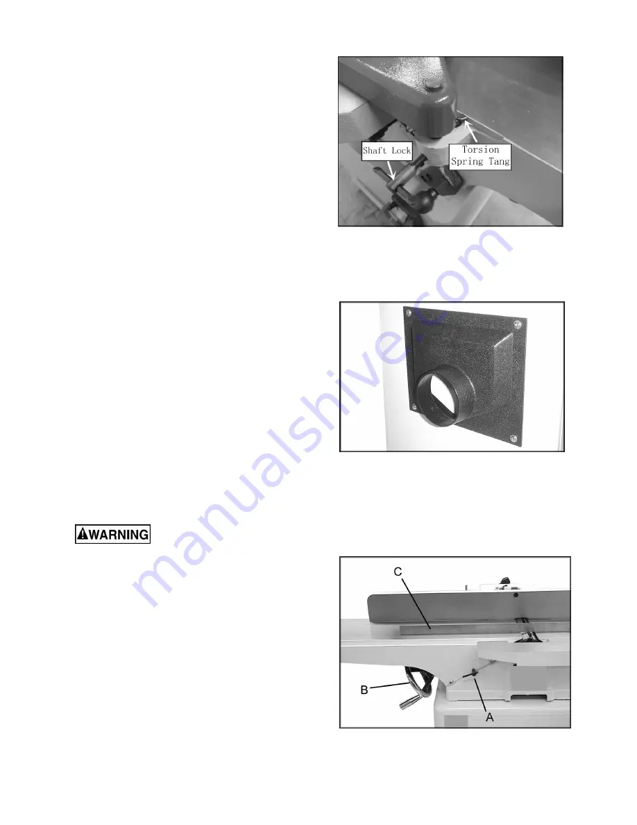
1. Place a strightedge(C Fig. 9) on the out- 

Figure 9 

reset the outfeed table hight as following: 

the outfeed table hight before use, if it is changed, 

However, it may change during the shipment, check 

Setting Outfeed Table Hight 

Attach the dust chute (Fig. 8) to the stand with 

Figure 8 

repeat STEP 1&2, increasing the spring tension

-If the guard does not snap back, remove it and 

-If the guard drags across the table, raise it until

2. Test the guard by pulling in back and  

1. Wind the tang the torsion spring back a  

so the spring tang points tp the right and reset 

half turn, and slide the guard shaft into the casting 

Figure 7 


Installing Cutterhead Guard 


Installing Dust Chute


four screws and four flat washers, through the 
pre-tapped holes in the stand. 


against the casting.(Fig. 7)

letting go.

-The guard should snap back over the cutterhead

without dragging across the table. If it does,

tighten the shaft lock.

it won't drag, then tighten the shaft lock.

as needed.

Machine should be 

disconnected from power source at this 
time! Cutterhead blades are extremely sharp! 
Use caution when hands are near the 
cutterhead!  

For most jointing operations, the surface of the 
outfeed table must be level with the knife tips of 
the cutterhead at their highest point of 
revolution. The knife tips must project equally 
from the cutterhead. 

The outfeed table and cutterhead are adjusted 
at the factory and should not require adjustment. 

Содержание WPLANE-200

Страница 1: ...Operating Instructions and Parts List 8 inch Professional Jointer ...

Страница 2: ...arning 5 Specifications Unpacking and Cleanup Unpacking and Cleanup Installing Bed to Stand Installing Handwheels Installing V Belts Installing Cutterhead Guard Installing Dust Chute Adjustments 90 Fence Adjustment 45 Fence Adjustment 12 Removing and Replacing Knives Replacing or Rotating Knife Inserts Gib Adjustment Operation Jointing Warped Material Direction of Grain Bevel Cut Taper Cut Rabbet ...

Страница 3: ...ies depending on how often you do this type of work To reduce your exposure to these chemicals work in a well ventilated area and work with approved safety equipment such as face or dust masks that are specifically designed to filter out microscopic particles 10 Do not operate this machine while tired or under the influence of drugs alcohol or any medication 11 Make certain the switch is in the OF...

Страница 4: ...26 Maintain tools with care Keep knives sharp and clean for the best and safest performance Follow instructions for lubricating and changing accessories 27 Turn off the machine and disconnect from power before cleaning Use a brush or compressed air to remove chips or debris do not use your hands 28 Do not stand on the machine Serious injury could occur if the machine tips over 29 Never leave the m...

Страница 5: ... Number of Knives 4 8 W x 1 2 D Identification Specifications Cutting Capacity Cutterhead Speed 5500 RPM Rabbeting Capacity Net Weight Jointer and Stand approx Shipping Weight Jointer and Stand A Outfeed Table B Infeed Table C Fence D Fence Tilt Handle E Outfeed Table Handwheel F Infeed Table Handwheel G Outfeed Table Lock H Infeed Table Lock I 1 8 Depth Stop J Magnitic Switch K Cutterhead Guard L...

Страница 6: ...Note Unit shipped in one crate and one carton Unpacking and Cleanup Contents of Shipping Cartons 1 12 14mm Open End Wrench 1 8 10mm Open End Wrench Tools Required for Assembly 1 Cross Point Screwdriver 6 8 Adjustable Wrench or 17 19mm Wrench Unpacking and Cleanup 1 Carefully finish removing all contents from both shipping cartons Compare contents of the shipping cartons with the list of contents a...

Страница 7: ...nism to 2 Line up two holes in top of stand with holes 3 Attach bed assembly to stand with two 3 8 lock bolts and lock washers Fig 2 Hand tighten only at this time 4 Line up third hole in stand with hole in bed assembly by viewing through dust chute 5 Install third 3 8 lock bolt and lock washer through dust chute to secure bed to stand 6 Tighten all three mounting bolts with 14mm wrench Figure 1 F...

Страница 8: ...rew fence holder Fig 5 2 Line up the hole on the fence and thread on on the fence holder Fig 5 with the two cap screws Fig 4 1 Lossen and take off the cap screw attached 4 Attach the fence carriage to jointer make sure Installing Fence Carriage to Jointer Installing Fence to Fence Carriage surface tighten the cap screws the surface of carriage level with jointer table 3 Line up two open holes on t...

Страница 9: ...4 2 Remove the lock knob A Fig 4 and belt Figure 4 Installing V Belts 1 Disconnect the machine from the power source unplug 3 Place v belts onto cutterhead pulley grooves and through opening in stand the v belt does not contact the sides of the opening in the base If the pulleys are not motor base and slide the motor until the belt is aligned Re tighten screws 6 The v belt is properly tensioned wh...

Страница 10: ... guard shaft into the casting Figure 7 Installing Cutterhead Guard Installing Dust Chute four screws and four flat washers through the pre tapped holes in the stand against the casting Fig 7 letting go The guard should snap back over the cutterhead without dragging across the table If it does tighten the shaft lock it won t drag then tighten the shaft lock as needed Machine should be disconnected ...

Страница 11: ...en edge C Fig 9 on the outfeed table and 9 Counter clockwise will cause the 3 Loosen table lock screw A Fig 9 and is at top dead center TDC as shown cutterhead pulley until one of the knives Figure 10 2 Rotate the cutterhead by turning the raise the outfeed table to the height of blade number one by turning handwheel B Fig outfeed table to raise Clockwise will cause the outfeed table to lower Set ...

Страница 12: ...STEP 3 contact with the 90 swing stop 4 Adjust the 90 fence stop bolt until it makes 3 Lossen the jam nut on the 90 fence stop bolt Fig 15 in Fig 15 2 Flip the 90 swing stop into the position shown Figure 15 90 position as shown in Fig 14 1 Using a 90 square adjust the fence to the To Set The 90 Fence Stop Note Whenever making an adjustment to the fence lift the fence up slightly after releasing t...

Страница 13: ...ce to the 135 45 inward position 1 Using a sliding bevel adjusted to 135 adjust Note Whenever making an adjustment to the fence lift the fence up slightly after releasing the lock handle to avoid scratching the table Gib Adjustment After a period of use the gibs may become loose and need adjusting 2 Tighten each set screw 1 4 turn starting at the bottom and working up If a 1 4 turn does not remove...

Страница 14: ...assembly clean all parts thoroughly and clear cutterhead knife slots of any dust or debris 5 Insert knife into the cutterhead channel making sure it faces the proper direction 6 Insert lock bar and screws and tighten to hold in place Blades are set at the proper height when the top of the blade is 1 16 above the cutterhead 7 Repeat for other two blades 8 To set the knives to the outfeed table and ...

Страница 15: ...ws are tightened securely Loose inserts can be propelled at high speed from a rotating cutterhead causing injury Operation Keep all guards in place and in adjustment at all times during the cutting procedure Keep hands away from the cutterhead Do not pass hands directly over the cutterhead The use of push sticks and or handle pads are highly recommended when using the jointer Failure to comply may...

Страница 16: ...erate speed If you feed the material too slowly the wood will burn in places If you feed the material too quickly ridges will appear in the finished surface Jointing Warped Material If the work to be jointed is cupped or warped take light repetitive cuts until the surface is flat Forcing the material flat against the table will still leave a warped piece after the cuts have been made Never joint a...

Страница 17: ...ncreasing depth leaving a tapered surface The ridge left by the knives when starting the taper may be removed by taking a very light cut in the regular jointing procedure with the infeed table raised to its normal position Practice is required in this operation Beginners are advised to make trial cuts with scrap material Rabbet Cut Rabbeting requires the removal of the cutterhead guard Use extreme...

Страница 18: ...e cutterhead pulley The infeed table height is set properly when the stone s surface is flush with the knife bevel 6 Keep the cutterhead from rotating by grasping the cutterhead pulley while sliding the stone back and forth across the table 7 Take the same amount of passes for all three blades When the blades have been sharpened if they still are not cutting efficiently trying to touch up the blad...

Страница 19: ...ut deeper than the middle Ends of tables are higher than middle Raise table ends with adjustment screws below tables Infeed or outfeed tables are loose Loose gib Tighten gibs One blade set higher than the others Readjust blades Feeding wood too fast Feed wood more slowly Ripples on planed surface Kickbacks Cutting blades are set too high above outfeed table or they may not be Motor Have motor chec...

Страница 20: ...RIPCTION QTY 28 WASHER 8 2 29 KEY 1 30 ROLL PIN 4 12MM 1 31 GUARD PIVOT SHAFT 1 32 ROLL PIN 6 40 1 33 ROLL PIN 6 35MM 1 34 CUTTER HEAD GUARD 1 35 RETURNING RING 12MM 1 37 NUT M8 6 38 SET SCREW M8 x 40 4 39 SMIALL SHAFT 3 40 KEY 5 x 5 x 25 2 41 HAND WHEEL 2 42 HAND WHEEL KNOB 2 43 WASHER 6 2 44 CAP SCREW M6 x 16 2 45 ANSI B18 6 7M M8x1 25 x 80 2 46 CUT HEAD WARNING 1 47 SCALE 1 48 DEPTH POINT 1 49 ...

Страница 21: ... BOLT M6 8 16 6 LOCK WASHER 10 2 7 STUD 2 8 WASHER 2 9 NUT M10 2 10 CUTTERHEAD PULLEY 1 11 KEY 5 30 1 12 SET SCREW M5 10 1 13 BALL BEARING 6204 2 14 BEARING BLOCK 2 ITEM DESCRIPCION QTY 4 7 8 9 11 13 10 12 7 8 9 CUTTERHEAD DIAGRAM AND PART LIST 1 14 14 3 5 2 6 6 13 ...

Страница 22: ...ESCRIPCION QTY 319 90 STOP TAB 1 320 FENCE TILT CLAMP 1 321 FENCE TILT SLEEVE 1 322 NUT M12 1 2 323 SET SCREW M6 8 2 324 NUT M8 2 325 CAP SCREW M8 x 40 2 326 CAP SCREW M8 x 20 3 327 WASHER 8 2 328 ANGLE GAUGE 1 329 SPECIAL SCREW 1 330 SHAFT 1 331 HANDLE POLE 1 332 KNOB 1 334 FLAT WASHER 2 335 STOP TAB 1 336 SPECIAL BOLT 1 337 RING 1 ITEM DESCRIPCION QTY 325 309 310 304 314 316 318 319 320 324 321 ...

Страница 23: ... 2 ITEM DESCRIPTION QTY 218 LOCK WASHER 5 2 219 GEAR WASHER 5 2 220 CAP SCREW M5 12 2 222 RUBBER FOOT M8 15 4 223 NUT M8 4 224 STAND 1 225 CHUT COLLECTOR 1 226 MOTOR 1 227 MOTOR PLATE 2 228 FLANGE NUT M8 8 229 LOCK WASHER 8 4 230 FLAT WASHER 8 8 231 BOLT M8 25 8 232 MOTOR PULLEY 1 233 KEY 8 45 1 234 SET SCREW M5 10 1 ITEM DESCRIPTION QTY 201 211 203 205 206 207 208 209 212 213 214 215 216 218 219 ...

Отзывы: