R3-TC2
5-2-55, Minamitsumori, Nishinari-ku, Osaka 557-0063 JAPAN
Phone: +81(6)6659-8201 Fax: +81(6)6659-8510 E-mail: [email protected]
EM-8468 Rev.3 P. 5 / 37
FUNCTION DESCRIPTIONS
■
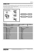
UNIVERSAL INPUT
• Input types
1) DC: 0 − 20mA / -1000 − +1000mV / -10 − +10V
2) Potentiometer: Max. total resistance 4000Ω
3) Resistor: Max. 4000Ω
4) RTD: Pt 100 / Pt 500 / Pt 1000 / Pt 50Ω / JPt 100 /
Ni 508.4Ω / Cu 10
5) Thermocouple: (PR) / K / E / J / T / B / R / S / C / N / U /
L / P
• Two input points can be assigned respectively with one of
the selections (1) through (5).
• Sampling cycle: 100 milliseconds
• Burnout detection available for potentiometer, resistor,
RTD and thermocouple inputs
• Cold junction compensation sensors for thermocouple in-
put included in the product package
• Fine input adjustment available
• DC, potentiometer and resistor inputs can be scaled into
temperature ranges.
• First order lag filter for input signals
■
CONTROL OUTPUT
• Output types
1) 12V pulse / 0 − 20mA DC / 0 − 10V DC
selected by model number suffix code when ordering
2) Open collector
• Two output points by the selection (1) plus two output
points with the selection (2)
• Control cycle 0.1 to 99.9 seconds
(100 msec. fixed for control output 0 − 20 mA and 0 − 10
V DC)
• Output resolution 1 millisecond
• PV, SP and MV signals can be scaled and provided as duty
ratio output; Alarm contact output (ON/OFF) also available
• Minimum ON/OFF pulse width can be specified for relay
life protection
■
CONTROL LOOP
• Control strategies
1) Standard PID control
2) Heating-cooling PID control
(independent PID operation for heating and cooling)
3) Heating-cooling ON/OFF control
(heating-only or cooling-only output is possible.)
• Two control loops can be assigned respectively to one of
the selections (1) through (3).
• Limit cycle method auto-tuning
• Direct/reverse action selectable for standard PID control
• Input 2 can be cascaded to loop 1 as its SP (remote SP)
• MV tracking function: MV in manual mode is carried on
into auto mode.
• High/low limits selectable for SP and MV values
• Specific MV values applicable at STOP/abnormality.
• Three PV alarm modes selectable for each loop
• Four bank settings available for each loop; Banks can be
switched during operation.
• Bank setting
• SP / SP rise ramp / SP fall ramp / P / I / D / Cooling P /
Cooling I / Cooling D / Heating sensitivity / Cooling sensi-
tivity / Deadband / PV alarm high/low limits
■
EVENT INPUT
• Two discrete input points can be assigned to a specific
event.
• Event types
• Switching banks / Switching operation / Switching manu-
al/auto mode / Switching local/remote SP
■
CT INPUT
• Input type
M-System clamp-on current sensor (model: CLSE)
• Two input points can be assigned respectively to monitor
specific control output status.
• One signal can watch heater wire break, SSR shortcircuit
failure and overload at once.
• Control output must be turned on for at the minimum
of 110 milliseconds to detect a heater wire break; must
be turned off for at the minimum of 200 milliseconds to
detect an SSR shortcircuit failure.
■
COMMUNICATION
• Monitoring and setting can be performed easily with PC
Configurator Software (model: R3CON).
• Various values can be read out via network communica-
tion (data allocation mode: 8)
• Modbus interface module (model: R3-NM3) available with
the R3 extension area communication realizes a large ca-
pacity data reading/writing.


