R3-TC2
5-2-55, Minamitsumori, Nishinari-ku, Osaka 557-0063 JAPAN
Phone: +81(6)6659-8201 Fax: +81(6)6659-8510 E-mail: [email protected]
EM-8468 Rev.3 P. 14 / 37
■
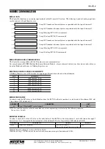
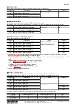
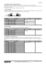
SETPOINT VALUE SETTING
SP for each loop can be changed via Modbus.
ADDRESS
PARAMETER
RANGE
DEFAULT
+6
Loop 1, Local SP (setpoint value)
-3200.0 to +3200.0
(decimal by input 1/2 decimal setting)
---
+14
Loop 2, Local SP (setpoint value)
These registers are overwritten by the SP in bank setting when the power supply is turned off or when the bank is switched.
Write the SP in the bank setting if the values should be maintained.
■
COMMAND EXECUTION
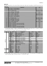
Predefined commands for each loop can be issued via Modbus by writing in the following addresses.
ADDRESS
PARAMETER
RANGE
DEFAULT
+64
Loop 1, Command
See the table below.
---
+65
Loop 2, Command
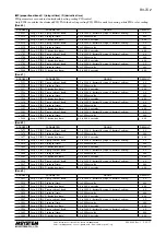
Available commands are as in the table below:
COMMAND
PARAMETER
1
Set loop operation to RUN
2
Set loop operation to STOP
3
Set control mode to AUTO
4
Set control mode to MANUAL
8
Reset all latched alarms in the loop
9
Reset all latched PV alarms
10
Reset all latched CT alarms
16
Switch to Bank 0
17
Switch to Bank 1
18
Switch to Bank 2
19
Switch to Bank 3
24
Run auto-tuning in the conditions specified by Bank 0
25
Run auto-tuning in the conditions specified by Bank 1
26
Run auto-tuning in the conditions specified by Bank 2
27
Run auto-tuning in the conditions specified by Bank 3
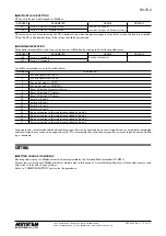
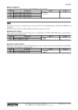
Loop operation, control mode and bank switching operation can be executed by an event input, however, using both commands
and event inputs may cause an unexpected result. We recommend that a function assigned to an event input be not controlled
by a command.
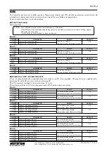
SETTING
■
SETTING CHANGE VIA MODBUS
Reading and writing via Modbus from the host is possible by the Network Module (model: R3-NM3).
Parameters are listed with Modbus address and data size in this manual. Access Holding Registers at these addresses to read
and write to refer and change settings.
Refer to “COMMUNICATION” section for the procedure.


